
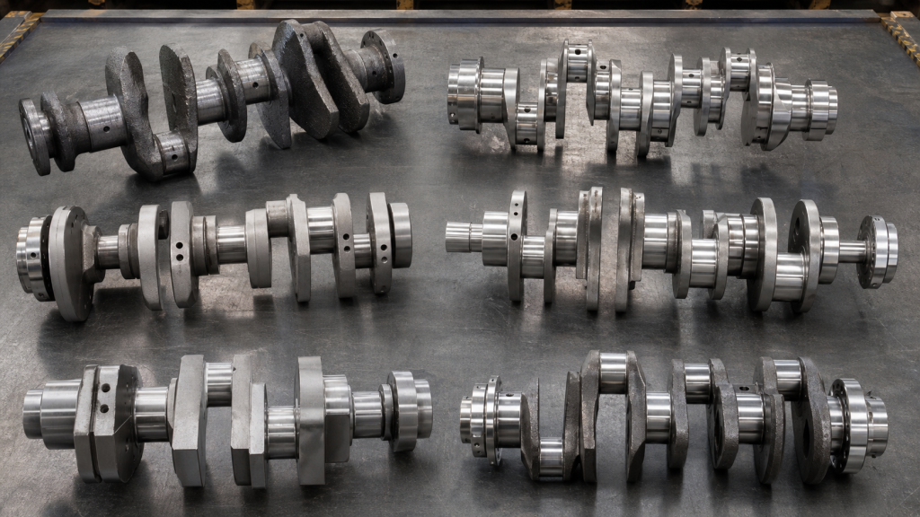
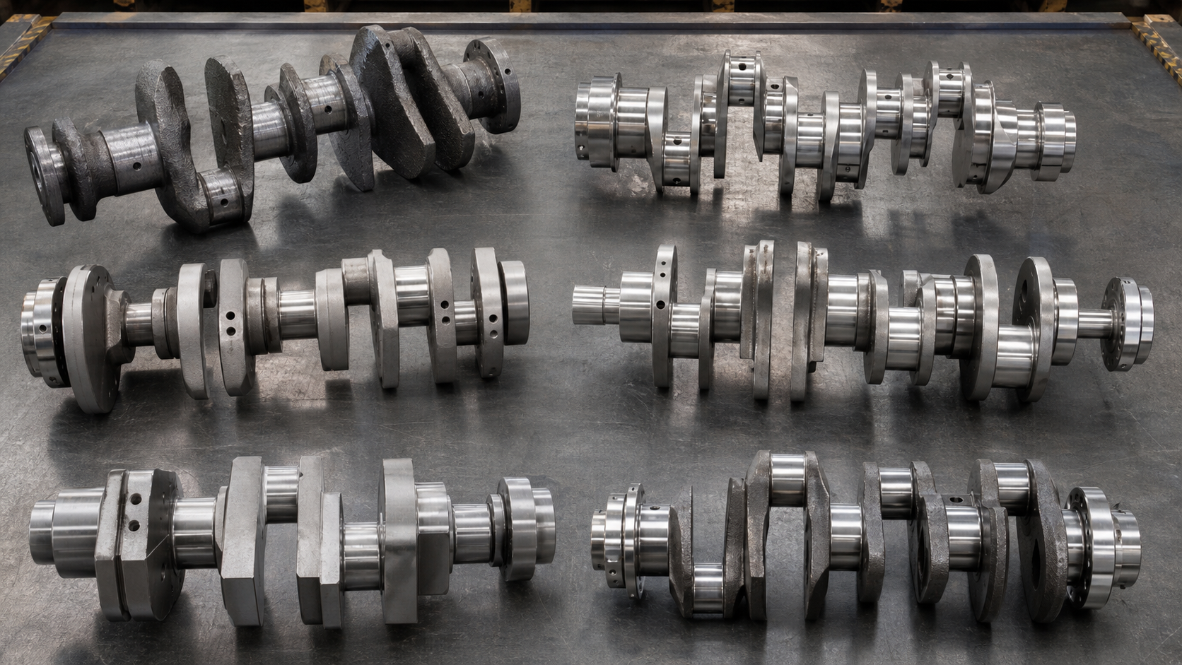
Crankshaft types are most clearly understood when separated into two independent classification axes: manufacturing route (cast, forged, or billet-machined) and structural architecture (one-piece, built-up, semi-built, and crankpin arrangement such as flat-plane or cross-plane). Mixing these categories—listing "forged" alongside "built-up" or "flat-plane"—creates confusion because they describe different design decisions. A forged crankshaft can be either one-piece or built-up. A built-up crankshaft can use cast, forged, or machined components. Flat-plane and cross-plane describe the angular spacing of crankpins, not the material or assembly method. Engine rebuilders, OEM sourcing engineers, and replacement-parts buyers should verify the engine maker’s drawing, material specification, and duty requirements before selecting a type, because universal interchange claims ignore measurable differences in journal size, fillet radius, counterweight placement, and dynamic balance limits.
Key Takeaways
- Classify crankshafts by manufacturing route (cast, forged, billet) and structural architecture (one-piece, built-up, semi-built) to avoid mixing unrelated attributes.
- Cast crankshafts dominate high-volume automotive production; forged crankshafts serve diesel, truck, and high-stress applications; billet-machined crankshafts support racing, prototypes, and low-volume custom builds.
- Built-up and semi-built designs allow large marine and industrial engines to split the crankshaft into separately manufactured and assembled throws, reducing forging size limits and simplifying repair.
- Flat-plane and cross-plane crankpin arrangements affect firing order, balance, and vibration but do not by themselves determine material strength or fatigue life.
- Selection requires engine model verification, measured journal dimensions, oil-passage configuration, and confirmation that the replacement matches the original drawing or approved service procedure.
Classify Crankshafts by Manufacturing Route and Architecture
Most online lists mix manufacturing methods, structural assembly types, and crankpin arrangements into a single flat hierarchy. This approach fails when a buyer needs to replace a failed crankshaft because it does not separate what the part is made from (material route), how it is assembled (one-piece or built-up), and how the crankpins are arranged (flat-plane, cross-plane, or other). A diesel engine OEM sourcing a forged one-piece cross-plane crankshaft cannot use a list that presents "forged," "built-up," and "cross-plane" as three competing types.
The first axis is manufacturing route: cast, forged, or billet-machined. This determines grain structure, fatigue strength, production volume, and cost. Cast crankshafts are poured into molds and offer good damping and moderate strength. Forged crankshafts are shaped under high pressure and provide superior grain flow and fatigue resistance. Billet-machined crankshafts are cut from solid bar stock and allow custom geometry but require more machining time.
The second axis is structural architecture: one-piece, built-up, or semi-built. One-piece crankshafts are continuous forgings or castings used in most automotive and truck engines. Built-up crankshafts assemble separate throws onto a central shaft, common in large marine diesels. Semi-built designs weld or shrink-fit selected throws onto a forged backbone. Flat-plane and cross-plane describe crankpin angular spacing and belong to a third, independent axis related to cylinder layout and firing order.
Cast Crankshafts
Cast crankshafts are produced by pouring molten iron or steel into sand or permanent molds. Ductile iron (nodular iron) is the dominant casting alloy for automotive applications because it combines acceptable tensile strength, good machinability, and internal damping that reduces vibration transmission. Cast steel crankshafts appear in some industrial and stationary engines where higher strength is required but forging cost cannot be justified.
The casting process creates a uniform microstructure without directional grain flow. Fillet radii, oil passages, and counterweights are formed during the pour, minimizing subsequent machining. This makes cast crankshafts the lowest-cost option for high-volume production. However, the lack of grain alignment around stress concentrations limits fatigue life compared to forged designs. Cast crankshafts typically operate in applications with lower peak loads and duty cycles than forged equivalents.
Surface treatments such as induction hardening of main and rod journals extend service life by increasing wear resistance. Nitriding improves surface hardness without distortion but adds cost. Most OEM cast crankshafts in passenger-car gasoline engines rely on untreated ductile iron with as-cast or machined journals. Fleet maintenance programs specify journal diameter and runout limits from the engine maker’s service manual rather than assuming universal interchange between casting sources.
Forged Crankshafts
Forged crankshafts are shaped from heated steel billets under hydraulic or mechanical presses. The forging process aligns the metal’s grain structure along the crankshaft’s load paths, creating superior fatigue strength and resistance to bending and torsional stress. Forged steel crankshafts dominate diesel engines, commercial trucks, marine propulsion, and high-performance gasoline applications where sustained high loads and elevated speeds exceed the capability of cast designs.
Common forging alloys include AISI 1045, 1050, 4140, and 4340 steels. Medium-carbon steels like 1045 and 1050 offer good strength and moderate cost. Alloy steels such as 4140 and 4340 provide higher hardenability and toughness, required when operating conditions demand greater wear resistance. The crankshaft manufacturer selects the alloy based on the engine’s peak firing pressure, rated speed, and duty cycle.
Inspection of forged crankshafts requires measurement of main and rod journal diameters, journal taper, journal out-of-round, and total indicated runout (TIR). Journals are checked with micrometers at multiple positions along the bearing surface. Runout is measured with a dial indicator while the crankshaft rotates in V-blocks or between centers. The engine maker’s drawing specifies the acceptable limits for journal taper and maximum runout. Exceeding these limits requires regrinding to an undersize or, if undersize limits are exhausted, replacement.
Magnetic particle inspection (MPI) detects surface and near-surface cracks in the fillet radii and oil-passage intersections, the two highest-stress zones. Cracks that propagate from these areas cause sudden fracture under load. MPI must follow the engine maker’s procedure or an equivalent approved standard. Ultrasonic testing detects internal flaws but is less common in field inspection because access to calibrated equipment and trained personnel is limited.
Billet-Machined Crankshafts
Billet crankshafts are machined from solid steel bar stock rather than cast or forged into near-net shape. The machining process removes material to create the main and rod journals, counterweights, and oil passages. Billet designs allow custom stroke, journal spacing, and counterweight configuration without the cost of dedicated forging dies or casting patterns. This makes billet crankshafts the preferred choice for racing engines, prototype development, and low-volume custom builds where tooling cost exceeds material and machining cost.
The absence of grain flow alignment is the primary trade-off. While the billet material itself (often 4340 or EN24 steel) has high tensile strength, the lack of forged grain structure reduces fatigue life under cyclic loading. Failure risk increases when billet crankshafts are installed in sustained high-load applications such as commercial diesel or marine propulsion without adjusting service intervals or stress levels. Racing applications mitigate this by frequent inspections, short service life, and controlled operating envelopes.
Oil-passage routing in billet crankshafts requires careful design because drilled passages must not intersect at acute angles or create stress risers. Cross-drilling from the main journal to the rod journal must maintain adequate wall thickness and fillet radii. Some billet designs use gun-drilled passages with plugged ends rather than intersecting holes to preserve structural integrity. The billet crankshaft guide provides additional machining and design considerations.
Billet crankshafts used in production engines must be validated with the same fatigue testing and dimensional inspection as forged designs. Custom fabrication does not exempt the part from meeting the engine maker’s balance, runout, and surface-finish requirements. Buyers requesting a billet replacement for a failed forged crankshaft should provide the original drawing, measured failure location, and operating-condition data to determine whether the billet design will survive the application.
One-Piece, Built-Up, and Semi-Built Marine Designs
One-piece crankshafts are continuous forgings or castings used in nearly all automotive, truck, and most industrial engines. The entire crankshaft is produced as a single unit, providing maximum rigidity and simplicity. Main journals, rod journals, counterweights, and oil passages are integral to the forging or casting. One-piece construction limits crankshaft length to the capacity of available forging presses and heat-treatment furnaces.
Built-up crankshafts overcome size limitations by assembling individual throws (one crank web, one rod journal, and one crank web) onto a central shaft with shrink fits, hydraulic fits, or mechanical keys. Large marine diesel engines and some slow-speed industrial engines use built-up designs because forging a single piece of sufficient length is impractical or unavailable. Each throw can be separately manufactured, inspected, and replaced. If a single journal fails, the throw can be removed and a new one installed without scrapping the entire crankshaft.
Semi-built crankshafts combine forged sections with welded or shrink-fitted inserts. A common semi-built configuration uses a forged backbone with individual counterweights welded or keyed into position. This approach reduces forging complexity while retaining most of the fatigue strength of a one-piece design. Semi-built designs appear in medium-speed diesels and industrial applications where one-piece forgings would be feasible but cost or lead time favor segmented construction.
The assembly joints in built-up and semi-built crankshafts require precise machining and controlled interference fits to prevent fretting, loosening, or misalignment under load. Hydraulic expansion or cryogenic shrinkage is used to assemble the throws onto the shaft. After assembly, the complete unit is dynamically balanced and inspected for runout. Maintenance intervals for built-up crankshafts include periodic checks of joint integrity, typically by ultrasonic or dye-penetrant inspection at the fit interfaces.
Flat-Plane, Cross-Plane, and Other Crankpin Arrangements
Flat-plane and cross-plane describe the angular relationship between crankpins when viewed along the crankshaft axis. These arrangements determine firing order, primary and secondary balance forces, and exhaust-pulse timing. They do not describe the material, manufacturing route, or assembly method.
A flat-plane crankshaft positions all crankpins in two planes 180 degrees apart. In an inline four-cylinder engine, this creates a firing order like 1-3-4-2 with even 180-degree crank intervals. Flat-plane designs generate secondary vertical imbalance forces but allow simpler exhaust manifold design and even exhaust-pulse spacing, improving scavenging in naturally aspirated and turbocharged engines. Flat-plane crankshafts are common in inline-four and V8 racing engines where high-revving operation benefits from reduced rotational inertia and shorter, stiffer crankshaft construction.
A cross-plane crankshaft staggers crankpins at 90-degree intervals. In a V8 engine, this arrangement yields a firing order like 1-8-4-3-6-5-7-2 with uneven exhaust-pulse spacing but superior primary and secondary balance. Cross-plane crankshafts dominate production V8 engines in trucks, marine, and automotive applications where smooth operation and low vibration are priorities. The additional counterweighting and longer crankshaft length increase rotational inertia, limiting peak engine speed compared to flat-plane equivalents.
Other crankpin arrangements include three-plane designs for inline six-cylinder engines (each pair of cylinders shares a crankpin plane, spaced 120 degrees apart) and split-pin designs where adjacent cylinders’ connecting rods share a single crankpin with an offset or forked small-end. The engine maker’s design specifies the arrangement based on cylinder count, firing order, vibration targets, and packaging constraints. Replacement crankshafts must match the original arrangement or the engine will not run correctly due to incorrect valve timing, injection timing, or balance.
Selection Table by Duty, Volume, and Service Requirement
Manufacturing Route | Structural Architecture | Typical Application | Production Volume | Repairability | Key Selection Criteria |
|---|---|---|---|---|---|
Cast ductile iron | One-piece | Passenger car gasoline engines, light-duty diesel | High-volume | Regrind to undersize; replace when limits exhausted | OEM part number, journal diameters, runout limits from service manual |
Forged steel (1045, 4140) | One-piece | Diesel truck, marine, industrial, high-performance gasoline | Medium to high volume | Regrind, inspect fillets, MPI; multiple undersize steps available | Engine drawing, peak cylinder pressure, rated speed, required fatigue life |
Forged steel (4340, EN24) | One-piece | Racing, sustained high-load diesel, performance rebuilds | Low to medium volume | Frequent inspection, limited regrind; shorter service life accepted | Custom stroke, balance factor, fillet radii, oil-passage routing |
Billet machined (4340) | One-piece | Racing, prototype, custom engine builds | Low-volume | Custom regrind possible but limited by grain structure; frequent replacement | Drawing or CAD model, measured failure data, validated dynamic balance |
Forged or cast sections | Built-up or semi-built | Large marine diesel, slow-speed industrial | Very low volume | Individual throws replaceable; joints inspected by UT or MPI | Assembly drawing, shrink-fit interference, joint inspection procedure |
Buyers must verify the replacement crankshaft matches the engine’s measured main and rod bearing bore diameters, stroke, counterweight mass, and dynamic balance requirements. A crankshaft from a different engine model, even with the same cylinder count, may not fit or may cause vibration, bearing failure, or interference with connecting rods or block casting. The crankshaft repair decision guide addresses when regrinding is acceptable and when replacement is required.
FAQs
Can a cast crankshaft be upgraded to a forged crankshaft without other engine modifications?
No, unless the engine maker offers both cast and forged crankshafts for the same engine model with identical external dimensions, bearing sizes, and balance specifications. Forged crankshafts are often heavier, require different counterweighting, and may change the engine’s balance factor. The connecting rod small-end height, piston pin height, and block clearances must be verified. Simply installing a forged crankshaft without confirming dimensional compatibility and dynamic balance can cause bearing failure, piston-to-head interference, or excessive vibration.
How do I determine if a used crankshaft is reusable?
Measure main and rod journal diameters at multiple points with a micrometer to detect taper and out-of-round. Check total indicated runout with a dial indicator while rotating the crankshaft in V-blocks or between centers. Compare all measurements to the engine maker’s service limits. Inspect fillet radii and oil-passage exits with magnetic particle inspection or dye-penetrant inspection for cracks. If journal dimensions are within tolerance, runout is acceptable, and no cracks are present, the crankshaft can be reused. If journals are undersize but still within the manufacturer’s undersize limits and surface finish is acceptable, the crankshaft can be used with undersize bearings.
What is the difference between a forged steel crankshaft and a billet steel crankshaft in terms of material properties?
Both use similar steel alloys (4140, 4340), but forged crankshafts have grain flow aligned along the crankshaft’s load paths due to the hot-working process, increasing fatigue strength and resistance to crack propagation. Billet crankshafts are machined from bar stock with random grain orientation. The base material strength is equivalent, but the lack of optimized grain flow reduces the billet’s fatigue life under cyclic loading. Forged crankshafts are preferred for production engines and sustained high-load applications; billet crankshafts are acceptable for racing, prototypes, and low-cycle-count custom builds where frequent inspection or replacement is planned.
Are flat-plane crankshafts stronger than cross-plane crankshafts?
No. Crankpin arrangement does not determine strength. A flat-plane crankshaft can be cast, forged, or billet-machined, and a cross-plane crankshaft can use the same manufacturing routes. Strength depends on material, heat treatment, fillet radii, and journal dimensions. Flat-plane crankshafts are often lighter due to simpler counterweighting, which reduces rotational inertia and allows higher engine speeds, but this is not the same as greater structural strength. Cross-plane crankshafts require more counterweight mass to balance the 90-degree crankpin spacing, increasing weight but improving vibration characteristics.
Can a crankshaft be repaired if a journal is worn beyond the final undersize limit?
In most cases, no. Once a journal diameter has been ground to the smallest undersize bearing available from the engine maker, further grinding removes too much material and weakens the journal. The crankshaft must be replaced. Some specialized rebuilders offer metal spray or welding processes to build up worn journals, followed by machining back to standard size, but this requires validation of fatigue strength and is not approved by most OEMs. The engine maker’s repair manual or service bulletin is the authoritative source for acceptable repair limits.
Conclusion
Selecting the correct crankshaft type requires separating manufacturing route (cast, forged, billet) from structural architecture (one-piece, built-up, semi-built) and crankpin arrangement (flat-plane, cross-plane). Cast crankshafts serve high-volume automotive production where moderate loads and cost control are priorities. Forged crankshafts meet the fatigue and strength demands of diesel, truck, marine, and high-performance engines. Billet-machined crankshafts support custom builds and racing where tooling cost outweighs material cost. Built-up and semi-built designs solve the forging-size limits of large marine and industrial engines. Before ordering a replacement or specifying a new crankshaft, measure the existing main and rod journal diameters, verify runout and taper, confirm the engine model and drawing number, and consult the crankshaft manufacturer with the complete dimensional data and operating conditions to ensure the replacement matches the required duty, balance, and service life.