
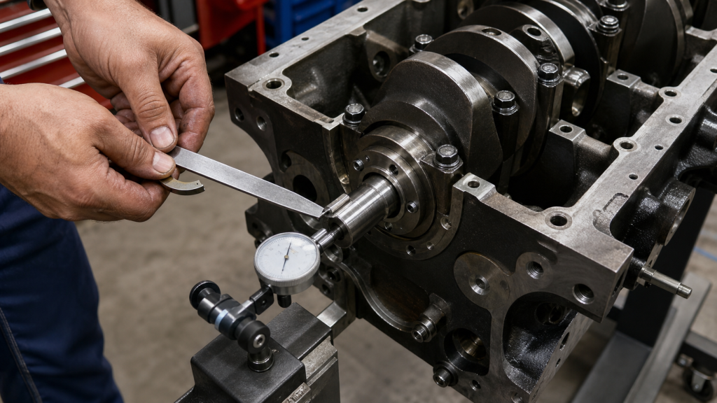
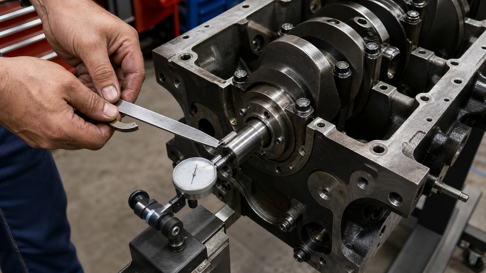
The crankshaft thrust bearing controls axial movement of the crankshaft inside the engine block. When you push the crankshaft forward or backward with a pry bar and measure the travel with a dial indicator, you are checking crankshaft end play—the total axial clearance between the thrust bearing surfaces and the crankshaft thrust faces. Excessive end play allows the crankshaft to shift during clutch engagement, torque converter loading, or accessory drive tension, leading to oil film breakdown, thrust face wear, and eventual bearing failure. Before replacing a damaged thrust bearing, you must measure the actual clearance, identify the load that exceeded the bearing’s capacity, and verify that the replacement part matches the engine maker’s specification and the crankshaft’s measured geometry.
This article walks through the measurement sequence first, then traces the axial loads and symptoms that cause thrust bearing failure, and ends with the verification steps that prevent recurrence.
Key Takeaways
- Crankshaft end play is the axial clearance measured by pushing the crankshaft fully forward and backward with the dial indicator on the nose or flange.
- The acceptable end play limit depends on the engine model, crankshaft material, and thrust bearing design specified by the engine maker’s service manual or blueprint drawing.
- Excessive end play produces axial knock during clutch engagement, torque converter stall, or accessory belt loading, and leaves polished or grooved wear patterns on the thrust faces.
- Automatic transmission torque converters apply continuous rearward thrust during lockup and high-torque conditions, making thrust bearing failure more common in automatic setups than manual transmissions.
- Always measure the crankshaft thrust face width, parallelism, and runout before installing new thrust bearings; a worn or out-of-spec thrust surface will destroy the replacement bearing in the same failure mode.
- Correct the root cause—misaligned torque converter, overloaded clutch, bent crankshaft, or assembly error—before finalizing the repair.
What the Thrust Bearing Controls
The thrust bearing is a set of hardened steel or bronze-backed bearing shells installed on one main journal, usually the center or rear main, with flanged surfaces that contact machined thrust faces on the crankshaft. These flanges prevent the crankshaft from moving axially while allowing rotation. The crankshaft experiences axial loads from the clutch pressure plate, torque converter pilot, helical timing gears, accessory belt misalignment, and combustion side loads on angled connecting rods. The thrust bearing absorbs these forces through a hydrodynamic oil film between the bearing flange and the crankshaft thrust face.
When end play is within specification, the oil film isolates the metal surfaces and distributes the axial load across the full thrust face width. When clearance is too tight—zero or negative end play—the crankshaft binds during thermal expansion, crushing the bearing material and scoring the thrust faces. When clearance is too loose, the oil film cannot maintain consistent thickness, and metal-to-metal contact occurs during load reversals. Both extremes accelerate wear and produce noise, vibration, or oil pressure loss.
The crankshaft journal article covers radial bearing surfaces and oil film requirements in detail; this article focuses on the axial control function and its unique failure modes.
Measure Crankshaft End Play with a Dial Indicator
To measure crankshaft end play, mount a magnetic-base dial indicator with the plunger tip against the crankshaft nose, flange, or a main journal counterweight face. Zero the dial indicator, then use a large pry bar between a main journal counterweight and the engine block to push the crankshaft fully forward. Record the dial reading. Next, pry the crankshaft fully rearward and record the second reading. The difference between the two readings is the total end play.
For example, if the forward position reads +0.003 inch and the rearward position reads -0.005 inch, the total end play is 0.008 inch (the difference between the two readings). The acceptable range varies by engine design, crankshaft construction, bearing type, and intended application. Always refer to the engine maker’s service manual, blueprint drawing, or class rule for the acceptable range. Using a generic tolerance can result in binding or excessive wear for your specific crankshaft and bearing design.
When measuring, ensure the crankshaft rotates freely and is not bound by accessory drives or a misaligned bellhousing. If end play exceeds the maximum specification, inspect the thrust bearing flanges and crankshaft thrust faces before ordering replacement parts. If end play is below the minimum specification, check for incorrect thrust bearing thickness, reversed bearing shells, or debris trapped between the bearing flange and thrust face.
Axial Loads from the Clutch, Torque Converter, and Assembly
The crankshaft experiences axial thrust from several sources. In manual transmission applications, the clutch pressure plate applies a forward load during disengagement when the throwout bearing pushes the pressure plate fingers. This load is transient and typically smaller than the thrust bearing’s capacity. In automatic transmission applications, the torque converter applies a continuous rearward load through the pilot hub, especially during lockup and high-torque conditions. The magnitude depends on torque converter stall speed, lockup strategy, and transmission line pressure.
Thrust bearing failure is more common in automatic transmission setups because the torque converter maintains constant contact with the crankshaft pilot, and any misalignment or excessive endplay in the converter itself translates directly to the crankshaft. If the transmission bellhousing is not parallel to the engine block face, or if the torque converter pilot hub is worn or out of specification, the converter can apply a side load that tilts the crankshaft and overloads one edge of the thrust bearing flange.
Accessory drives with misaligned pulleys or excessive belt tension can also generate axial loads. Helical timing gears produce a continuous axial component due to the helix angle, and this load must be absorbed by the thrust bearing. During assembly, improper main bearing cap torque sequence, incorrect thrust bearing installation, or failure to check end play before final tightening can preload the thrust bearing or leave excessive clearance.
Symptoms of Tight, Loose, or Damaged Thrust Surfaces
Excessive crankshaft end play produces a distinct axial knocking or tapping sound during clutch engagement, torque converter stall, or sudden throttle changes. The noise occurs when the crankshaft slams against the thrust bearing flange after traveling through the clearance gap. Unlike radial main bearing knock, which is rhythmic and tied to crankshaft rotation, thrust bearing knock is event-driven and may disappear under steady load.
Insufficient end play causes the crankshaft to bind during thermal expansion, producing drag, increased oil temperature, and eventual thrust face galling. The engine may be difficult to rotate by hand after a heat cycle, and the starter may draw excessive current. If the binding is severe, the thrust bearing material can extrude from between the bearing shell and the block, leaving visible smearing or metal transfer.
Physical inspection of a failed thrust bearing reveals polished, grooved, or heat-discolored thrust faces on the crankshaft. The bearing flange may show embedded metal particles, copper alloy smearing, or complete loss of the overlay material. If wear is concentrated on one side of the thrust face, suspect bellhousing misalignment or a bent crankshaft. If both sides are worn evenly, the failure likely resulted from excessive axial load or insufficient oil supply to the thrust bearing groove.
Oil pressure may drop if thrust bearing debris circulates through the oiling system and clogs the oil pump pickup screen or restricts flow to other main or rod bearings. Always flush the oiling system and inspect the oil pump after a thrust bearing failure.
Correct the Cause Before Installing New Thrust Bearings
Before installing new thrust bearings, measure the crankshaft thrust face width, parallelism, and surface finish. The thrust face must be flat across its width, and both sides must be parallel to prevent edge loading. Consult the engine maker’s rework limit to determine whether a worn thrust face can be resurfaced or requires crankshaft replacement. Attempting to compensate for a worn thrust face by using oversize thrust bearings will not restore the correct oil film geometry and will fail again under load.
Check bellhousing alignment with a dial indicator mounted to the crankshaft flange. Refer to the engine maker’s specification or class rule for the maximum allowable total indicated runout at the bellhousing bore. If the bellhousing is out of alignment, use offset dowel pins, shims, or a different bellhousing to correct the misalignment before final assembly. For automatic transmissions, verify torque converter pilot hub length, runout, and fit in the crankshaft pilot bore. A loose or worn pilot hub can allow the converter to wobble and apply uneven thrust loads.
Select thrust bearings that match the crankshaft’s measured thrust face width and the engine maker’s specified clearance. Thrust bearings are available in standard and oversized flanges to accommodate resurfaced thrust faces. Install the bearing shells with the flange facing the correct direction—most engines place the thrust bearing flanges against the rear main journal, but some designs use the center main. Apply assembly lube to the thrust faces and flanges, but do not use excessive sealant that could block the oil feed hole.
After torquing the main bearing caps to specification, measure end play again before installing the timing cover, oil pan, and transmission. If end play is still out of specification, determine whether the problem is undersized thrust bearing flanges, worn crankshaft thrust faces, or incorrect bearing selection. For billet or forged crankshafts in custom engine builds, verify that the thrust face width and journal dimensions match the bearing design before machining the block.
FAQs
Can I reuse thrust bearings if end play is within specification?
No. Thrust bearings develop a wear pattern that conforms to the crankshaft thrust face and bearing flange. Once removed, the bearing cannot be reinstalled in the same orientation and position with confidence. The oil film geometry depends on consistent surface contact, and any disturbance during disassembly disrupts that contact. Replace thrust bearings whenever the crankshaft is removed, even if the measured end play was acceptable before disassembly.
What causes thrust bearing failure on engines with manual transmissions?
Manual transmission thrust bearing failures typically result from aggressive clutch engagement, worn pilot bushings, or bellhousing misalignment. When the clutch pedal is released abruptly at high rpm, the pressure plate applies a sudden forward load to the crankshaft through the clutch disc. If the pilot bushing is worn or missing, the input shaft can wobble and apply side loads to the clutch disc, which transfers to the crankshaft. Inspect the pilot bushing and bellhousing alignment whenever thrust bearing wear appears on a manual transmission engine.
How does thrust bearing design differ between forged and cast crankshafts?
Forged crankshafts typically have tighter geometric tolerances than cast crankshafts, and the thrust bearing selection must match the crankshaft’s manufacturing method, material, and measured geometry. Cast crankshafts may require wider bearing flanges to distribute the axial load over a larger area. When sourcing replacement crankshafts, verify that the thrust face width, journal dimensions, and oil hole locations match the original design or the updated bearing set specified by the engine maker or bearing supplier.
Can excessive crankshaft runout cause thrust bearing failure?
Yes. If the crankshaft has excessive radial runout at the thrust bearing journal, the thrust bearing flanges will lift off the thrust face during rotation, breaking the oil film and allowing metal-to-metal contact. Measure crankshaft runout at all main journals and the thrust bearing journal before assembly. If runout exceeds the engine maker’s limit, the crankshaft must be straightened or replaced. Runout cannot be corrected by adjusting bearing clearances or thrust bearing thickness.
What is the correct oil clearance for the thrust bearing flanges?
The axial clearance between the thrust bearing flange and the crankshaft thrust face is the end play measurement covered earlier in this article. The radial clearance between the thrust bearing journal and the bearing shell is the main bearing oil clearance, which is specified separately by the engine maker. Both clearances must be within specification for proper oil film formation. Do not confuse axial end play with radial oil clearance; they are independent measurements with different failure modes.
Conclusion
Crankshaft thrust bearing failure begins with excessive axial loads, insufficient oil film, or geometry errors that overload the bearing flanges. The diagnostic sequence starts with a dial indicator end play measurement, then traces the load path backward through the torque converter, clutch assembly, and crankshaft geometry to identify the root cause. Replacing the bearing without correcting bellhousing alignment, torque converter condition, or crankshaft thrust face wear will result in repeat failure. Before ordering a replacement crankshaft or thrust bearing set, measure the existing crankshaft thrust face width, parallelism, and surface finish, and confirm that the new parts match the engine maker’s drawing and the measured block geometry. For guidance on crankshaft manufacturing methods and their implications for thrust bearing selection, consult the engine manufacturer’s technical documentation or an experienced crankshaft supplier.