
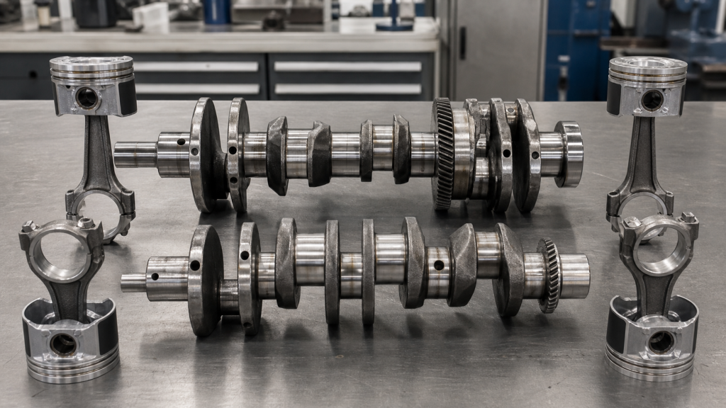
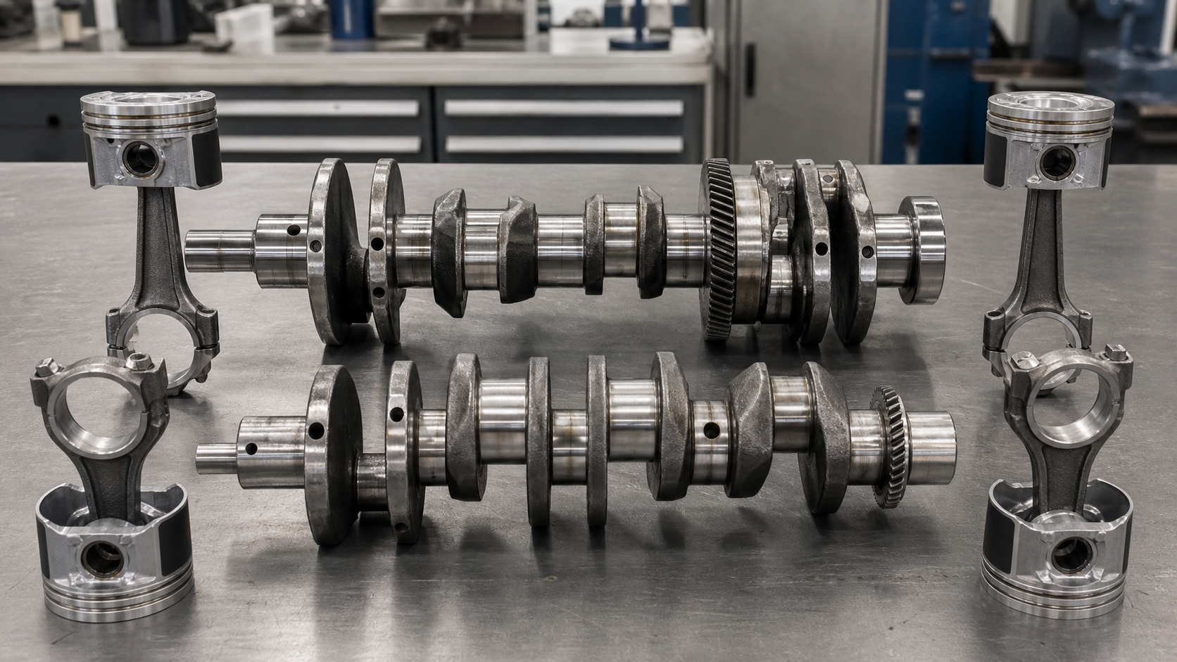
Two crankshafts built on the same main-journal diameters and installed in the same cylinder bore can deliver dramatically different displacement, torque characteristics, and piston speeds when their crankshaft stroke differs. Stroke is the vertical distance the piston travels from bottom dead center to top dead center, and it equals twice the offset between the crankshaft centerline and the rod-journal centerline—the crank radius. A longer stroke increases leverage on the rod journal, raises mean piston speed, and demands taller deck height or shorter rods. A shorter stroke allows higher engine speeds before piston acceleration limits are reached but sacrifices displacement unless bore diameter compensates. Understanding how stroke changes displacement, mechanical advantage, rod geometry, and packaging helps rebuilders, equipment owners, and OEM sourcing engineers select the correct crankshaft manufacturer specification, verify measurements during inspection, and predict the consequences of a stroker conversion.
Key Takeaways
- Crankshaft stroke equals twice the crank radius, measured as the perpendicular distance from the crankshaft centerline to the rod-journal centerline.
- Displacement scales linearly with stroke when bore and cylinder count remain constant; a 10% stroke increase delivers a 10% displacement increase.
- Longer stroke increases leverage at the rod journal and lowers the engine speed at which mean piston speed reaches a given limit, affecting durability and valve-train demands.
- Rod ratio (connecting-rod length divided by stroke) drops when stroke increases without lengthening the rod, changing piston dwell near top dead center and side-loading the cylinder wall.
- Stroker crankshaft projects require coordinated changes to piston compression height, deck height, counterweight mass and profile, and main-bearing oil clearance to maintain balance and clearance.
Stroke Is Twice the Crank Radius
Crankshaft stroke is defined as the distance the piston travels from bottom dead center (BDC) to top dead center (TDC) in one direction. Geometrically, stroke equals twice the crank radius—the perpendicular offset from the crankshaft’s main-journal centerline to the center of the rod journal (crankpin). When the crankshaft rotates 180 degrees, the rod journal moves from its lowest point to its highest point, and the piston follows that motion through the connecting rod. Because the rod journal traces a circle around the main-journal centerline, the vertical displacement is twice the radius of that circle.
Two crankshafts machined with identical main-journal diameters, main-bearing spacing, and overall length can still produce different strokes if their rod journals are offset at different radii. For example, a stock crankshaft with a 50 mm crank radius delivers a 100 mm stroke. A stroker crankshaft built on the same main journals but with a 55 mm crank radius increases stroke to 110 mm, raising displacement by 10% if bore and cylinder count remain unchanged. The main-bearing caps, block register, and oil-gallery positions remain compatible, but the increased rod-journal swing path requires verification of piston-to-valve clearance, rod-to-camshaft clearance, and counterweight-to-block clearance.
Crank radius is measured with a dial indicator mounted to the crankshaft and zeroed at the main-journal centerline, or by using a caliper to measure the vertical distance between the top of one main journal and the top of an adjacent rod journal when the crankshaft is positioned with that rod journal at TDC. Stroke is then double that measurement. This measurement confirms whether a crankshaft matches the engine maker’s specification or a stroker kit’s claimed dimensions before assembly begins.
Calculate Displacement from Bore, Stroke, and Cylinder Count
Engine displacement is the total swept volume of all cylinders and depends on bore diameter, stroke, and the number of cylinders. The formula is:
Displacement = (π / 4) × Bore² × Stroke × Number of Cylinders
Where:
- Bore is the cylinder diameter in millimeters or inches
- Stroke is the crankshaft stroke in millimeters or inches
- π / 4 ≈ 0.7854
- Result is in cubic millimeters or cubic inches; divide by 1,000 to convert mm³ to cm³ (cc), or by 1,000,000 to convert to liters
Worked Example:
A four-cylinder engine with an 86 mm bore and a 86 mm stroke has:
Displacement = 0.7854 × (86 mm)² × 86 mm × 4
Displacement = 0.7854 × 7,396 mm² × 86 mm × 4
Displacement = 1,998,826 mm³ ≈ 1,999 cc ≈ 2.0 liters
If the stroke is increased to 94.6 mm using a stroker crankshaft while bore remains 86 mm:
Displacement = 0.7854 × (86 mm)² × 94.6 mm × 4
Displacement = 2,198,708 mm³ ≈ 2,199 cc ≈ 2.2 liters
The 10% stroke increase (from 86 mm to 94.6 mm) produces a 10% displacement increase (from 2.0 L to 2.2 L) when bore and cylinder count are held constant. This linear relationship makes stroke the most straightforward way to increase displacement without reboring the cylinders, provided the block, rods, and pistons can accommodate the geometry changes.
Displacement limits are set by the engine maker’s block casting, bearing design, valve timing, and intended operating range. Exceeding those limits without recalibrating fueling, ignition, and cooling can lead to detonation, oil starvation, or overheating. Always verify that the target displacement falls within the maker’s approved stroker-kit range or obtain a revised approval before committing to machining or part orders.
Longer Stroke Changes Leverage and Mean Piston Speed
Increasing crankshaft stroke changes two linked performance characteristics: leverage at the rod journal and mean piston speed.
Leverage:
Torque applied to the crankshaft depends on the force the connecting rod transmits to the rod journal and the perpendicular distance (moment arm) from the crankshaft centerline to the line of that force. When stroke increases, the rod journal moves farther from the crankshaft centerline at the point of maximum cylinder pressure, which typically occurs shortly after TDC during the power stroke. This greater radius increases the mechanical advantage, producing more torque for the same cylinder pressure. Longer-stroke engines tend to deliver higher torque at lower engine speeds, making them suitable for heavy equipment, trucks, and industrial applications where low-end pulling power matters more than peak horsepower.
Mean Piston Speed:
Mean piston speed quantifies how fast the piston moves on average during one complete stroke. It is calculated as:
Mean Piston Speed = 2 × Stroke × Engine Speed
Where:
- Stroke is in meters (divide millimeters by 1,000)
- Engine Speed is in revolutions per second (divide RPM by 60)
- Result is in meters per second (m/s)
Or equivalently:
Mean Piston Speed (m/s) = (2 × Stroke in mm × RPM) / 60,000
Worked Example:
A crankshaft with an 86 mm stroke running at 6,000 RPM produces:
Mean Piston Speed = (2 × 86 mm × 6,000 RPM) / 60,000 = 17.2 m/s
A stroker crankshaft with a 94.6 mm stroke at the same 6,000 RPM produces:
Mean Piston Speed = (2 × 94.6 mm × 6,000 RPM) / 60,000 = 18.92 m/s
The 10% stroke increase raises mean piston speed by 10% at the same RPM. Higher piston speeds increase inertia loads, accelerate ring and bore wear, stress the oil film in the wrist pin and rod bearings, and demand stiffer valve springs to prevent valve float. Engine makers specify maximum mean piston speeds based on bearing design, oil supply, cooling capacity, and material strength. A longer-stroke engine reaches that limit at a lower RPM, narrowing the usable speed range unless the application naturally operates at lower speeds.
Consult the engine maker’s service manual, technical bulletin, or approved stroker-kit documentation for the maximum piston speed specific to your engine family. These limits vary by design and cannot be generalized across all engine types.
Rod Ratio, Deck Height, Counterweights, and Packaging
Increasing crankshaft stroke without changing other geometry introduces mechanical tradeoffs that must be resolved during design or conversion.
Rod Ratio:
Rod ratio is the connecting-rod center-to-center length divided by stroke. When stroke increases and rod length remains constant, rod ratio drops. Lower rod ratios increase the angularity of the connecting rod at mid-stroke, which increases side-loading on the piston skirt and cylinder wall. This can accelerate bore wear, raise friction, and require stronger piston skirts or modified piston-pin offsets. Lower rod ratios also reduce dwell time near TDC, changing the burn profile and potentially requiring revised ignition timing. To preserve rod ratio during a stroker conversion, the connecting rod must be lengthened, which then requires shorter pistons or taller deck height.
Deck Height:
Deck height is the distance from the crankshaft centerline to the block’s head-gasket surface. When stroke increases, the piston travels farther down the bore at BDC. If the piston’s compression height (distance from the wrist-pin centerline to the piston crown) and the rod length remain unchanged, the piston crown will protrude above the deck at TDC or drop too far below the deck at BDC. The solution is to reduce piston compression height so the piston crown remains at or slightly below the deck surface at TDC. This maintains quench distance and combustion-chamber volume. Some stroker kits require a taller aftermarket block with increased deck height to accommodate longer rods while preserving quench.
Counterweights:
Longer stroke moves the rod journal’s center of mass farther from the crankshaft centerline, increasing the rotating and reciprocating unbalance. Counterweights must be enlarged or repositioned to restore balance. Stroker crankshafts often use crankshaft heat treatment such as nitriding or induction hardening on the enlarged counterweights to maintain fatigue strength while adding mass. Counterweight profiles must clear the block’s skirt, oil-pan rail, and camshaft during rotation. A crankshaft with adequate stroke may still fail to fit if the counterweights interfere with the block casting.
Main-Bearing Clearance:
Heavier counterweights and higher reciprocating forces increase the load on main bearings. Oil clearance, bearing material, and supply pressure must match the increased loads. Some stroker applications require upgraded main-bearing caps, cross-bolted mains, or girdle systems to prevent bearing walk or cap deflection under load.
These packaging constraints explain why a 10% displacement increase through stroke may require new pistons, rods, bearings, a different oil pump, revised head gaskets, and block machining—even when the main journals remain the same size. Confirm all clearances with the kit supplier’s fit instructions and verify bearing clearances with plastigage or a dial-bore gauge before final assembly.
Long-Stroke vs Short-Stroke Tradeoffs
Engine designers choose stroke length based on the application’s torque, speed, and packaging priorities. Long-stroke and short-stroke engines each carry distinct advantages and limitations.
Long-Stroke Engines (Undersquare: Stroke > Bore):
Long-stroke engines deliver higher torque at lower engine speeds due to the increased leverage at the rod journal. Mean piston speed reaches the material and lubrication limit at lower RPM, so peak power occurs at moderate speeds. This makes long-stroke designs well-suited for trucks, tractors, marine propulsion, and stationary power where low-end torque and fuel efficiency matter more than high-RPM power. The taller cylinder height increases engine overall height, which can complicate packaging in low-hood or transverse-engine layouts. Longer stroke also increases the surface area of the cylinder bore exposed during the stroke, which can improve thermal efficiency by reducing heat loss per unit of displaced volume.
Short-Stroke Engines (Oversquare: Bore > Stroke):
Short-stroke engines allow higher redlines before piston speed limits are reached. The shorter stroke reduces the vertical space required, enabling lower hood lines and more compact packaging. Shorter stroke also permits larger valves for a given displacement, improving breathing at high engine speeds. However, the reduced leverage at the rod journal means torque output at low RPM is lower unless cylinder pressure is increased through higher compression ratios, forced induction, or more aggressive cam timing. Short-stroke engines are common in high-performance applications, sportbikes, and racing where peak power and high-speed operation outweigh low-speed torque.
Square Engines (Bore = Stroke):
When bore equals stroke, the engine balances torque and speed characteristics. Many modern engines use near-square designs to optimize volumetric efficiency across a broad speed range while maintaining compact packaging.
Application-specific factors determine the correct stroke choice. A fleet manager replacing a truck crankshaft will prioritize torque at typical highway cruise speeds and durability at sustained loads, favoring a longer-stroke design. A performance engine builder targeting a high redline will choose a shorter stroke to keep mean piston speed within acceptable limits. Neither approach is universally better; each solves a different design problem.
What Must Change in a Stroker-Crankshaft Project
Converting an engine to a longer-stroke crankshaft—commonly called a "stroker" conversion—requires coordinated changes across multiple components. Planning these changes before ordering parts prevents clearance failures, balance problems, and repeated crankshaft failure.
Pistons:
The compression height must be reduced to maintain the correct piston-deck height at TDC. Piston manufacturers supply stroker-specific pistons with shorter compression heights matched to common stroke increases. The piston’s top ring land, skirt length, and pin boss must clear the increased rod angularity and crankshaft counterweights. Always verify that the piston skirt does not contact the crankshaft counterweight at BDC by performing a clay check or dry-fit rotation before final assembly.
Connecting Rods:
If the goal is to preserve or improve rod ratio, longer connecting rods are needed. The increased rod length may require shorter pistons, taller deck height, or both. Rod beam strength and bearing area must support the higher cylinder pressures that often accompany displacement increases. Upgraded rod bolts or a switch to billet or forged rods may be necessary to meet the load requirements.
Cylinder Block:
Deck height, bore diameter, main-bearing register, and oil-gallery locations must accommodate the new crankshaft, rods, and pistons. Some stroker kits fit within the stock block if the stroke increase is modest. Larger stroke increases require aftermarket tall-deck blocks with increased distance from the crankshaft centerline to the deck surface.
Crankshaft:
The stroker crankshaft must maintain the correct main-journal diameter, journal spacing, and flange pilot to fit the engine’s main bearings and flywheel. Counterweights must be sized and positioned to balance the increased stroke and heavier pistons. How crankshafts are manufactured determines whether the crankshaft is forged, cast, or billet. Forged and billet crankshafts offer higher strength and tighter tolerances but cost more than cast options. The crankshaft supplier should provide balance specifications so the rotating assembly can be balanced as a set with the flywheel, clutch, and harmonic damper.
Main and Rod Bearings:
Bearing clearances must be verified after installing the stroker crankshaft. Increased loads may require bearings with higher load capacity, improved oil-groove design, or upgraded bearing material. Oil pressure and flow must match the bearing clearances and the increased bearing surface speed caused by the larger rod-journal swing diameter.
Oil System:
Higher engine speeds and increased bearing loads may require a higher-volume or higher-pressure oil pump. Oil pan depth must provide adequate clearance for the longer-stroke crankshaft’s counterweights and rod big-ends at BDC. The oil pickup tube position may need adjustment to maintain the correct standoff distance from the pan floor.
Cylinder Head and Valvetrain:
Piston-to-valve clearance must be checked at TDC overlap and during maximum valve lift. Stroker pistons often use valve reliefs to accommodate valve intrusion. The valve timing, lift profile, and spring pressures may need adjustment to suit the new displacement and altered burn characteristics. Confirm that the camshaft’s base-circle diameter and lobe profile clear the increased rod big-end swing path.
Balancing:
The complete rotating assembly—crankshaft, flywheel, clutch, harmonic damper, rods, pistons, rings, pins, and fasteners—must be balanced together to a vibration level acceptable to the engine maker or class rules. External balance (counterweight mass on the harmonic damper or flywheel) or internal balance (counterweight mass machined into the crankshaft) depends on the engine design. Many stroker crankshafts shift from internal to external balance due to the increased reciprocating mass.
Stroker projects succeed when all geometry, clearance, and load requirements are verified against the engine maker’s drawings, the kit supplier’s instructions, and measured inspection data. A crankshaft manufacturer familiar with custom forged or billet crankshafts can assist with dimensional verification, material selection, and heat treatment when off-the-shelf stroker kits do not fit the application. Always request certification or test reports for critical dimensions, hardness, and material composition before committing to production or installation.
FAQs
Can I measure stroke without removing the crankshaft from the block?
Yes. With the spark plugs or injectors removed, rotate the crankshaft to bring one piston to TDC, zero a dial indicator or depth gauge on the piston crown, then rotate the crankshaft 180 degrees to BDC and measure the travel distance. That measurement is the stroke. Alternatively, insert a degree wheel and piston stop to locate true TDC, then measure the difference in piston height between TDC and BDC. This method confirms stroke during inspection or diagnosis without full teardown but does not verify crank-radius geometry or bearing clearances.
Does increasing stroke always require a new engine block?
Not always. If the stroke increase is modest and the block has adequate deck height, cylinder-wall thickness, and oil-pan clearance, the existing block may accommodate a stroker crankshaft with appropriate pistons and rods. Larger stroke increases or blocks originally designed with minimal clearances often require a tall-deck block or significant machining. The block’s main-bearing saddle, oil-gallery placement, and cam-bearing tunnel position must align with the new crankshaft geometry. Always verify clearances through CAD modeling or physical mock-up before machining or ordering parts.
What happens to rod ratio if I use a stock rod length with a stroker crankshaft?
Rod ratio decreases. For example, a 150 mm rod with an 86 mm stroke gives a rod ratio of 1.74:1. If stroke increases to 100 mm with the same 150 mm rod, rod ratio drops to 1.50:1. The lower ratio increases connecting-rod angularity at mid-stroke, raising side-load on the piston and cylinder wall. This can accelerate bore wear, increase friction, and require stronger piston-skirt designs or offset wrist pins to distribute the load. To maintain or improve rod ratio, use longer connecting rods along with the stroker crankshaft, which then requires shorter pistons or taller deck height.
Can I convert a short-stroke racing engine to a long-stroke setup for more torque?
Mechanically yes, but the entire rotating assembly and engine management must be redesigned. The short-stroke racing engine likely uses high-compression pistons, aggressive cam timing, large valves, and tuning optimized for high RPM and airflow. Switching to a long-stroke crankshaft increases displacement and lowers the RPM at which piston speed and bearing loads peak, but the existing compression ratio, cam profile, intake runner length, and exhaust tuning will be mismatched to the new torque curve and operating range. The conversion requires new pistons, revised cam timing, retuned fuel and ignition maps, and possibly different cylinder heads to suit the altered breathing requirements. The cost and complexity usually exceed building a dedicated long-stroke engine from the start.
How do I know if a crankshaft’s stroke matches the engine maker’s specification?
Measure the crank radius directly with a dial indicator or caliper as described earlier, then multiply by two to obtain stroke. Compare the result to the specification listed in the engine service manual, parts catalog, or maker’s technical bulletin. If the measured stroke deviates from the specification by more than the maker’s stated tolerance, investigate whether the crankshaft has been reground, replaced with an aftermarket part, or damaged. Some reground crankshafts use undersize main or rod journals, which changes the crank radius and stroke. Always verify the crankshaft part number, casting marks, and journal diameters against the maker’s identification guide before assuming the crankshaft is original or correct for the application.
Conclusion
Crankshaft stroke—twice the crank radius—directly controls engine displacement, torque leverage, and mean piston speed. Two crankshafts built on the same main-journal diameters but with different rod-journal offsets produce different displacements and operating characteristics, making stroke selection a primary design variable for matching engine behavior to application demands. Longer stroke increases low-speed torque and displacement but raises piston speed and requires coordinated changes to pistons, rods, deck height, counterweights, and clearances. Shorter stroke permits higher engine speeds and compact packaging but sacrifices displacement unless bore diameter compensates.
When planning a stroker conversion or selecting a replacement crankshaft, verify the target stroke against the engine maker’s specifications, measure crank radius to confirm the geometry, calculate the resulting displacement and mean piston speed, and confirm that all clearances, bearing loads, and balance requirements are met. A responsible crankshaft manufacturer will supply dimensional certification, material test reports, and balance data to support these checks. For custom or high-output applications, request a fit review that includes CAD clearance analysis or physical mock-up before committing to machining or production. Stroke is a powerful tool for tuning engine performance—but only when the complete mechanical system is designed, measured, and validated as a coordinated assembly.