
When you spot visible wobble at the front of a running engine, you are often looking at a crankshaft pulley that has either separated from its hub or lost the bonded-rubber element inside a harmonic damper assembly. The crankshaft pulley is the wheel mounted to the crankshaft’s front end that drives accessory belts. When that pulley is part of a harmonic balancer or vibration damper, it also contains a tuned rubber or elastomer layer designed to suppress torsional oscillations in the crankshaft. Misdiagnosing a simple pulley failure as a damper problem, or sourcing the wrong replacement, leads to repeat failures or new vibration damage. Before you remove anything, confirm whether your engine uses a solid pulley, a bonded damper, or a separate pulley and damper stack, then verify the failure mode with measurements rather than assumptions.
Key Takeaways
- A crankshaft pulley may be a simple belt wheel or part of a harmonic damper assembly; knowing which type your engine uses determines the correct replacement and failure analysis.
- Wobble, belt misalignment, and accessory-system faults are visible symptoms, but confirming the failure requires measuring runout and inspecting the damper rubber before removal.
- Removing the pulley without protecting the crankshaft nose threads, keyway, or timing reference can damage the crank or force a complete rebuild.
- Fitment depends on crank nose diameter, keyway dimensions, bolt specifications, and damper inertia tuning, all of which must match the engine maker’s drawing or approved parts list.
- When ordering a replacement, verify the part number against the engine serial prefix, accessory drive configuration, and any class or certification limits that apply to your application.
Pulley, Damper, and Harmonic Balancer Are Not Always the Same Part
The terms crankshaft pulley, harmonic balancer, and vibration damper are used interchangeably in many shop manuals, but they describe different mechanical assemblies. A crankshaft pulley in the simplest form is a machined or cast wheel, keyed or bolted to the crankshaft’s front end, that transmits rotation to one or more accessory belts. It has no internal damping element. Many passenger-car and light-truck engines use a harmonic balancer, which combines the pulley function with a bonded-rubber layer sandwiched between an inner hub and an outer inertia ring. The rubber element absorbs torsional vibration energy generated by combustion pulses and reciprocating-mass imbalance. A third configuration bolts a simple pulley to the front face of a separate viscous damper or tuned-mass damper, common in heavy-duty diesel and performance applications.
Identifying your engine’s configuration before diagnosis is not optional. A solid pulley that develops a crack or keyway wear will exhibit wobble, but the crankshaft itself remains dynamically balanced and the repair requires only a new pulley and keyway inspection. A bonded damper that has separated—rubber degradation or hub debonding—allows the outer ring to shift or spin independently, creating the same visible wobble but also removing the torsional damping that protects main and rod bearings from fatigue. Replacing a failed damper with a solid pulley will introduce vibration levels the engine was never designed to tolerate. Conversely, installing a damper on an engine that never required one adds rotating mass, changes accessory-drive geometry, and may interfere with the timing cover or front seal.
Check the engine maker’s parts diagram or measure the installed part. A solid pulley will have no visible seam or rubber layer when inspected from the side. A harmonic balancer will show a bonded joint or have a slightly larger diameter inertia ring compared to the hub. If a separate damper is present, you will see two distinct components: the damper hub bolted to the crank, and the pulley bolted to the damper face.
How the Crankshaft Pulley Drives Accessories and Controls Vibration
The crankshaft pulley transfers rotational energy from the crankshaft’s front end to the alternator, water pump, power-steering pump, and air-conditioning compressor through one or more serpentine or V-belts. The pulley diameter and the number of belt grooves determine the speed ratio for each accessory. Most modern engines use a single serpentine belt with automatic tensioning, but older or industrial engines may have separate belts for each accessory with fixed or adjustable mounting brackets.
When the pulley is part of a harmonic damper, the bonded-rubber element provides torsional damping. Combustion events and reciprocating-mass acceleration create torsional vibration in the crankshaft, a twisting oscillation that occurs at specific engine speeds determined by crankshaft stiffness, bearing compliance, and firing order. Without damping, these oscillations concentrate stress at the crankshaft’s fillet radii and can lead to fatigue cracks at the front journal or the first crankpin. The damper’s inertia ring is tuned to the engine’s natural torsional frequency, and the bonded rubber dissipates vibration energy as heat. The tuning is specific to the engine’s displacement, firing order, and operating range, which is why a damper from a different engine model—even if it physically fits the crank nose—will not provide correct damping.
In diesel and heavy-duty applications, the front pulley or damper also carries the timing mark or trigger wheel that synchronizes the engine-control module with crankshaft position. Damage to this reference surface or misalignment after installation will cause timing errors, misfires, or no-start conditions. Some performance engines add an additional damper at the rear of the crankshaft, but the front damper remains the primary torsional control because it is located at the free end of the crank where torsional amplitude is highest.
Failure Clues You Can Confirm Before Removal
Visible wobble is the most common clue, but it does not by itself tell you whether the pulley, the damper rubber, the hub-to-crank attachment, or the crankshaft itself has failed. Before removing the pulley, perform these checks with the engine off and the ignition disabled:
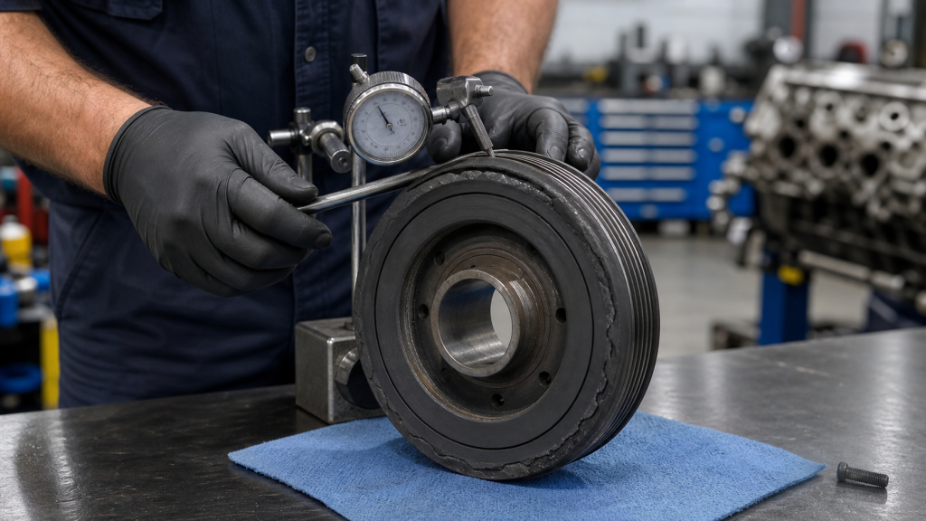
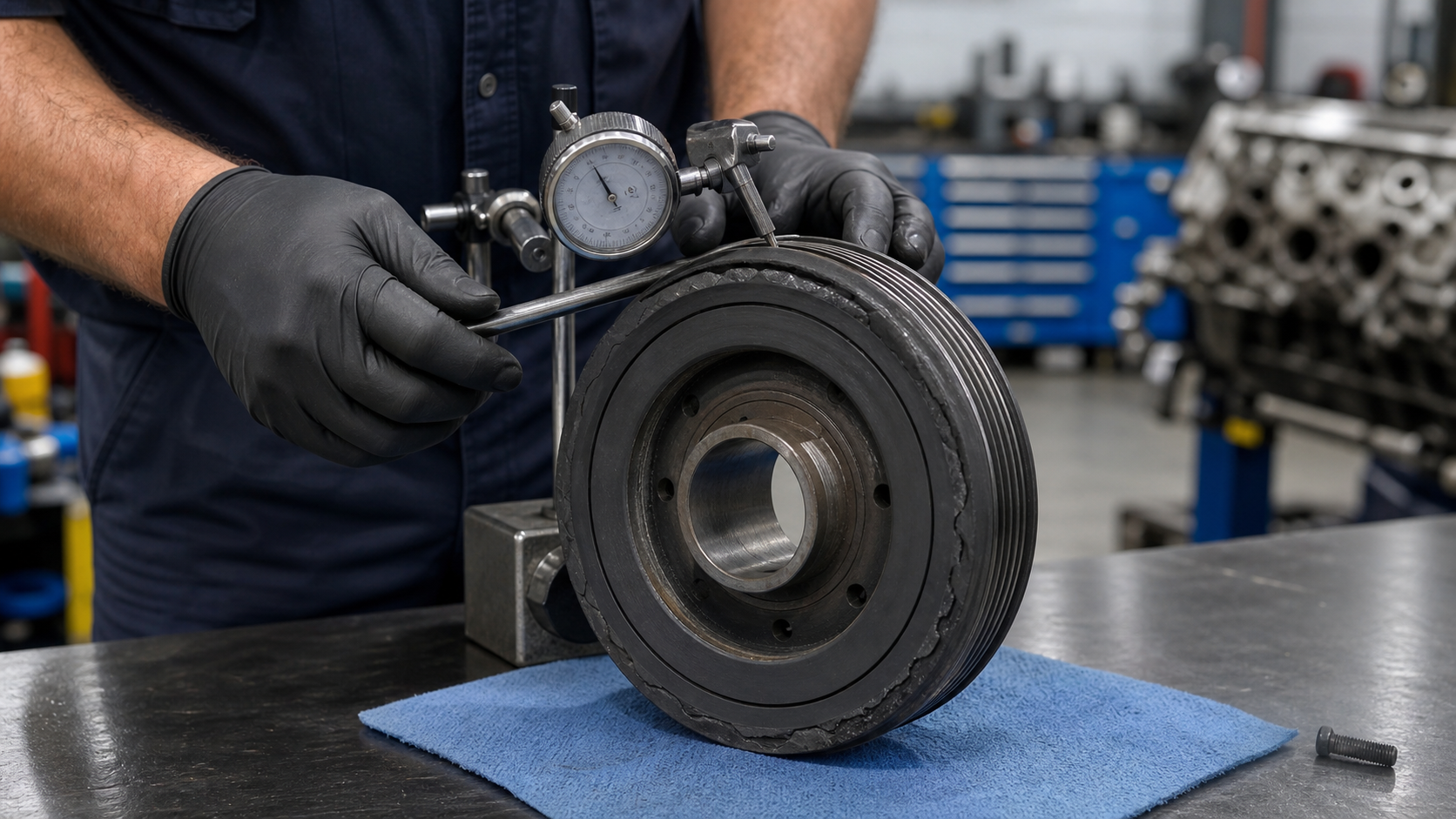
Runout measurement: Use a dial indicator mounted to the engine block or timing cover, with the probe tip against the outer face of the pulley or damper ring. Rotate the crankshaft by hand through one full revolution and record the total indicated runout (TIR). Consult the engine maker’s service manual for the maximum acceptable TIR for your specific engine. Runout exceeding that limit confirms mechanical separation, hub distortion, or crank-nose bending. If you see elevated runout but the engine has no other symptoms, recheck with the belt removed to eliminate belt-tension effects.
Belt-groove alignment check: If the engine uses multiple belts or a serpentine belt with automatic tensioning, inspect the belt path for misalignment. A pulley that has shifted axially on the crank nose or a damper ring that has rotated relative to its hub will push the belt out of the groove or cause one side of the belt to wear faster than the other. Measure the distance from the pulley face to a fixed timing-cover reference point and compare to the opposite side. Refer to the service manual for acceptable alignment tolerances.
Rubber-condition inspection: For bonded dampers, inspect the joint between the hub and the inertia ring. Look for cracks, separation gaps, or rubber that has extruded from the bond line. Press a small screwdriver or pick into the rubber surface; if it feels hard and brittle rather than slightly elastic, the rubber has aged beyond its service life and no longer provides damping. Some dampers have a witness mark or timing stripe painted across the hub and ring; if the stripe is discontinuous or offset, the ring has rotated relative to the hub and the damper has failed.
Keyway and bolt inspection: Remove the center bolt and inspect the keyway in both the crankshaft nose and the pulley hub. Keyway wear, fretting, or shear damage indicates the key has been overloaded, usually from improper bolt torque, missing thread locker, or a previous pulley slip. Measure the keyway width and depth and compare to the engine maker’s drawing. Worn keyways allow the pulley to shift circumferentially under load, creating timing errors if the pulley drives a sensor or carries a timing mark.
Accessory-system confirmation: Verify that the symptom is not caused by a seized accessory bearing. Disconnect or remove the belt and spin each accessory pulley by hand. A seized alternator or power-steering pump will drag the belt and create vibration or noise that appears to come from the crankshaft pulley. If all accessories spin freely and the runout measurement still exceeds limits, the fault is in the pulley or damper assembly.
Do not assume that noise or vibration alone confirms a pulley failure. Crankshaft repair procedures address main-journal runout, fillet cracks, and oil-passage blockages that can also cause front-end vibration. If your runout measurement is within limits but you still have vibration, the root cause may be in the crankshaft itself, requiring a full inspection before replacing the pulley.
Removal Methods That Protect the Crank Nose and Timing Reference
Removing a crankshaft pulley or damper without the correct tool risks damaging the crankshaft nose threads, bending the crank, or shearing the Woodruff key. The center bolt typically requires significant torque specified in the service manual and may have a thread-locking compound. Attempting to remove it with an impact wrench while the engine is in the vehicle can spin the crankshaft, bending valves if the timing chain or belt is still installed. Once the bolt is removed, the pulley hub is usually pressed onto the crank nose with an interference fit and must be pulled off with a harmonic-balancer puller, never hammered or pried.
Bolt removal sequence: Lock the crankshaft to prevent rotation. For manual-transmission vehicles, put the transmission in gear and apply the parking brake. For automatic transmissions, use a strap wrench around the pulley or a flywheel-holding tool accessed through the bellhousing inspection cover. Some engine makers provide a dedicated holding tool that engages the flywheel ring gear or a machined flat on the crankshaft flange. Never use a screwdriver or punch through the pulley to jam the crank; this will damage the timing cover or oil seal. Apply penetrating oil to the bolt threads and wait before attempting removal. Use a six-point socket and a breaker bar or calibrated torque wrench in reverse. If the bolt does not break free, apply heat to the bolt head—not the pulley—to break the thread locker.
Puller setup: Install a harmonic-balancer puller with bolts threaded into the tapped holes in the pulley face. Most pulleys have two or three tapped holes on a standard bolt circle. Do not thread the puller bolts into the damper’s inertia ring if it is a bonded unit; you must engage the inner hub only. Center the puller’s forcing screw on the crankshaft nose and verify that the puller legs are square to the pulley face. Tighten the forcing screw gradually while supporting the puller to prevent it from tipping. If the pulley does not move after moderate screw torque, apply heat to the pulley hub—not the crankshaft nose—and retry. Never strike the end of the crankshaft with a hammer; this can damage the front main bearing or propagate a crack into the first journal.
Timing-reference protection: If the engine uses a crank-position sensor that reads a trigger wheel or reluctor ring on the pulley or damper, note the position of the trigger wheel relative to the keyway before removal. Some trigger wheels are removable and can be transferred to the new pulley; others are integral and the new part must be clocked correctly during installation. Misalignment will cause the engine-control module to calculate incorrect injection or ignition timing. For engines with a painted timing mark on the damper, photograph the mark position or measure its distance from the keyway before removal so you can transfer the mark to the new damper if needed.
Crankshaft nose inspection after removal: Once the pulley is off, clean the crankshaft nose and inspect for damage. Measure the nose diameter at the seal contact area, the hub press-fit area, and the threaded section. Compare to the engine maker’s drawing. Scoring, fretting, or out-of-round conditions may require crank nose regrinding or a repair sleeve. Inspect the keyway for cracks or elongation. If the keyway is damaged, the crank must be removed for machine repair or replacement. Check the oil-seal bore in the timing cover for wear or scoring; a worn seal bore will cause a new seal to leak regardless of pulley condition.
Fitment Data to Check Before Ordering a Replacement
Ordering a replacement crankshaft pulley or harmonic damper based on engine model alone is insufficient for industrial, heavy-duty, or performance applications. Engine makers often use multiple pulley configurations within a single model series, varying by accessory-drive arrangement, belt type, or market regulation. The following dimensions and specifications must match the original part or the engine maker’s approved replacement list:
Crank nose diameter and length: Measure the crankshaft nose diameter at the press-fit area using a micrometer. The fit tolerance is typically specified as an interference fit, meaning the hub bore is slightly smaller than the crank nose. Measure the crank nose length from the front face of the first main journal to the end of the threaded section. The new pulley hub length must not bottom out on the thread relief or leave excessive crank nose exposed beyond the hub.
Keyway dimensions: Measure the keyway width, depth, and length in both the crankshaft and the pulley hub. Standard Woodruff key sizes follow industry designation systems, while metric engines use ISO-standard parallel keys. The keyway depth in the crank nose must match the key’s radial height, and the pulley hub keyway must provide sufficient engagement length as specified by the engine maker.
Center bolt specifications: Record the bolt thread size, length, and torque specification from the engine maker’s service manual. Some engines use a through-bolt that threads into the crankshaft nose; others use a shorter bolt with a large washer that clamps the pulley hub against a shoulder. Do not substitute a different bolt grade or length. Most engine makers specify a new bolt for each installation, as the bolt may be torque-to-yield or have a thread-locking patch that cannot be reused.
Damper inertia and tuning: For harmonic balancers, the inertia ring mass and damping characteristics are tuned to the engine’s firing order and displacement. A damper from a similar engine model will not provide correct damping if the displacement, stroke, or firing order differs. Cross-reference the part number against the engine serial prefix or build date to confirm compatibility. Aftermarket dampers may claim universal fitment, but universal dampers often provide inadequate damping at the engine’s critical torsional frequency, leading to accelerated bearing wear or crankshaft fatigue. When sourcing a replacement damper for a rebuilt or modified engine, provide the engine maker’s drawing number, displacement, and operating speed range to the damper supplier.
Accessory-drive configuration: Measure the pulley diameter and count the number of belt grooves. For serpentine-belt systems, the groove profile must match the belt type. For V-belt systems, measure the groove angle and pitch diameter. If the engine has been modified with aftermarket accessories or a different belt routing, verify that the new pulley diameter maintains the correct speed ratio for the alternator and water pump. Incorrect ratios will cause charging problems or overheating.
OEM vs. aftermarket considerations: When ordering from a crankshaft manufacturer, provide the engine maker’s part number, the engine serial prefix, and photographs of the installed pulley showing the hub, keyway, and bolt. For custom or modified engines, provide the crankshaft drawing with crank nose dimensions and material specification. Forged crankshafts and billet crankshafts may have different nose geometries than cast crankshafts from the same engine family. If the replacement is part of a crankshaft manufacturing rebuild or upgrade, confirm that the new pulley or damper is validated for the crankshaft material and expected service duty.
Dimension | Measurement Tool | Documentation Source |
|---|---|---|
Crank nose diameter | Micrometer | Engine maker drawing or service manual |
Hub bore diameter | Bore gauge or telescoping gauge | Pulley or damper part drawing |
Keyway width | Caliper or keyway gauge | ISO 3912 or ANSI B17.1 standard |
Center bolt torque | Torque wrench | Service manual or bolt manufacturer |
Pulley diameter | Caliper or tape measure | Accessory-drive layout drawing |
Damper inertia | Calculated from ring mass and radius | Damper manufacturer or engine validation report |
FAQs
Can I reuse a harmonic damper after removing it?
Most engine makers prohibit reusing a pressed-fit harmonic damper once it has been removed. The interference fit between the hub and the crankshaft nose can be reduced during removal, and the bonded rubber may have been stressed by the removal process even if no visible damage occurred. If you must reuse a damper, measure the hub bore diameter before and after removal to confirm the interference fit is maintained, and perform a runout check after reinstallation. If runout exceeds the service manual limit, the damper must be replaced.
What happens if I install a solid pulley on an engine designed for a harmonic damper?
Removing the torsional damping will increase crankshaft stress at the natural torsional frequency, which typically occurs in the mid-range operating speed. Bearing wear accelerates due to higher dynamic loads, and fatigue cracks can develop at the first main journal fillet or the front crankpin. Some racing classes permit removing the damper for weight reduction, but this requires a crankshaft material upgrade and a reduced operating speed range to avoid the critical torsional mode.
How do I know if my crankshaft nose is damaged and needs repair before installing a new pulley?
Measure the crank nose diameter at four points 90 degrees apart using a micrometer. Out-of-round exceeding the service manual tolerance indicates scoring or fretting wear. Inspect the seal contact area for grooves or steps; any groove depth that exceeds the tolerance will cause a leak even with a new seal. Check the keyway for cracks, elongation, or missing metal. Minor scoring can be polished out with fine abrasive cloth, but dimensional loss or cracks require the crankshaft to be removed and repaired. A repair sleeve can be installed over a worn seal area if the engine maker approves that method, but the sleeve must be machined to the original crank nose diameter and the pulley hub bore must be enlarged to match.
Do I need to apply thread locker or anti-seize to the crankshaft pulley bolt?
Follow the engine maker’s specification. Most modern engines use a torque-to-yield bolt with a factory-applied thread-locking patch that requires no additional compound. Older engines may specify thread locker on clean, dry threads. Never apply anti-seize compound unless the service manual explicitly requires it, as anti-seize reduces friction and can cause the bolt to be overtorqued, leading to bolt failure or crank nose damage. If the service manual gives a torque specification without a lubrication note, the torque assumes dry threads.
Can a crankshaft manufacturer supply a custom pulley or damper for a modified engine?
Custom pulleys and dampers are feasible when the engine maker’s original part is unavailable or when an engine has been modified beyond the original specification. The manufacturer requires the crankshaft drawing showing nose diameter, keyway dimensions, and material specification, along with the engine’s displacement, firing order, operating speed range, and accessory-drive requirements. For harmonic dampers, a torsional analysis or engine validation report may be required to confirm the correct inertia and damping characteristics. Small-batch or one-off custom parts do not receive the same field validation as production parts, so plan for dynamometer testing or instrumented field trials before committing to volume production.
Conclusion
A crankshaft pulley failure can appear as wobble, belt misalignment, or accessory-system faults, but the correct repair depends on separating a simple pulley from a tuned harmonic damper and confirming the failure with runout measurements before removal. Removing the pulley without the correct puller or crankshaft-locking method risks nose damage that forces a complete rebuild. Before ordering a replacement, measure the crank nose diameter, keyway dimensions, and pulley diameter, then cross-reference the part number against the engine serial prefix and accessory-drive configuration. For rebuilt or custom crankshafts, provide the engine maker’s drawing and operating-speed range to the supplier so the replacement damper is correctly tuned. Your next step is to verify the installed pulley type, measure runout with a dial indicator, and inspect the crankshaft nose for wear or damage before deciding whether to replace the pulley alone or address a deeper crankshaft issue.