
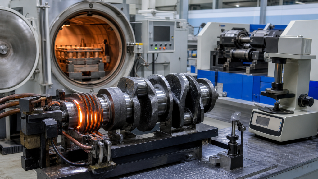
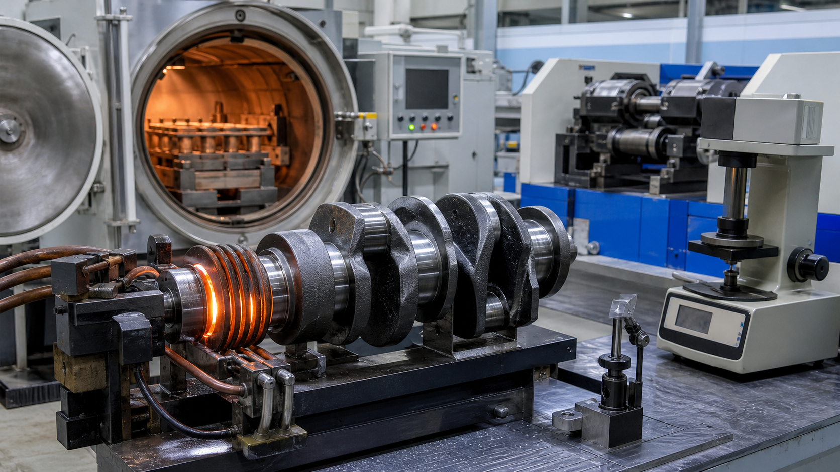
Crankshaft heat treatment is not a single operation but a sequence of thermal and mechanical processes applied to specific crankshaft features according to the engine maker’s design requirements. A forged diesel crankshaft for a heavy-duty truck engine typically moves through multiple control stations: bulk quench-and-temper for core strength, induction hardening of main and rod journals for wear resistance, gas nitriding of fillets and journals for fatigue strength, and fillet rolling for compressive residual stress. Each station has its own temperature, time, case-depth, and hardness targets, and each requires verification before the crankshaft advances. The engine maker’s drawing establishes which processes are mandatory, which surfaces receive treatment, and what inspection results constitute acceptance. A crankshaft without the specified heat treatment will fail prematurely under load, but the wrong heat-treatment sequence or missed verification can produce a part that looks correct yet cannot meet its duty cycle.
Key Takeaways
- Quench-and-temper establishes bulk tensile strength and toughness; induction hardening, nitriding, and fillet rolling address specific surface requirements and do not substitute for core properties.
- Induction hardening raises journal surface hardness for wear resistance; case depth and target hardness values are specified by the engine maker and must be verified by hardness traverse or metallographic section.
- Gas nitriding forms a thin, hard case with high residual compressive stress; it improves fillet fatigue life but requires temperature control below the prior tempering point to avoid softening the core.
- Fillet rolling is a mechanical cold-working process that induces compressive stress in the fillet radius; it complements but does not replace thermal treatments and must follow all heat-treatment steps to avoid stress relief.
- Every heat-treatment step requires process documentation and inspection records; missing verification or out-of-sequence operations are common causes of hidden crankshaft defects that appear only under service load.
Five Different Jobs Hidden inside the Term Heat Treatment
The term "heat treatment" in a crankshaft specification refers to at least four separate metallurgical processes plus one mechanical strengthening operation, each targeting a different failure mode. A quench-and-temper operation applied to the entire forging establishes the baseline tensile strength, yield strength, and impact toughness required by the steel grade and engine duty. Induction hardening of journals creates a wear-resistant surface for bearing contact. Gas nitriding deposits nitrogen into the surface to form hard nitrides and introduce compressive residual stress, improving fatigue resistance in fillets and other high-stress areas. Fillet rolling mechanically deforms the fillet radius to add further compressive stress. Each operation has its own temperature range, heating rate, time at temperature, cooling method, and inspection requirement.
A diesel truck crankshaft forged from medium-carbon alloy steel will typically receive all four thermal treatments plus fillet rolling, in that sequence. A cast nodular-iron crankshaft for a gasoline engine may receive only induction hardening of journals and fillet rolling, because the casting process and matrix structure do not support quench-and-temper or nitriding in the same way. The engine maker’s drawing specifies which treatments are mandatory, the order of operations, and the acceptance criteria for each step. Reversing the sequence—for example, nitriding before induction hardening—can produce a crankshaft with inadequate case properties or internal stress patterns that lead to distortion or cracking.
The control plan for a forged crankshaft follows the part from the forge through each heat-treatment station and records temperature, time, case depth, hardness, and distortion at defined intervals. This documentation proves that each operation met its target and that the final crankshaft is capable of meeting the engine’s load and duty cycle.
Core Strength from Steel Condition and Quench-and-Temper Practice
Quench-and-temper is the first heat-treatment operation on a forged steel crankshaft and establishes the core tensile strength, yield strength, and toughness that support all subsequent surface treatments. The forged crankshaft is heated to the austenitizing temperature—specified by the steel grade and drawing requirements—held at temperature until the entire cross section reaches equilibrium, then rapidly cooled (quenched) in oil or polymer to form martensite. The as-quenched martensite is hard but brittle, so the crankshaft is immediately reheated to a tempering temperature determined by the required strength-toughness balance, held for the specified time, then air-cooled. Tempering reduces hardness slightly but dramatically increases toughness and ductility.
The tempering temperature determines the final hardness and strength. Lower tempering temperatures increase hardness and strength but reduce impact toughness; higher tempering temperatures improve toughness but lower tensile strength. The engine maker selects the tempering temperature based on the crankshaft’s duty cycle, bearing load, and expected fatigue life. The steel supplier’s data sheet provides the strength-temperature relationship for each alloy grade.
The quench-and-temper operation must produce uniform properties throughout the crankshaft, including the journals, webs, and counterweights. Non-uniform cooling during quenching can produce soft spots or regions with insufficient toughness. The control plan requires hardness checks at multiple locations—typically one main journal, one rod journal, and one counterweight web—to verify uniformity. The hardness results and furnace temperature charts become part of the crankshaft’s traceability record.
Quench-and-temper does not produce the high surface hardness required for journal wear resistance. That requires a separate induction-hardening step after tempering.
Induction Hardening of Journals
Induction hardening heats only the journal surface using electromagnetic induction, transforming a shallow layer to austenite while the core remains at ambient temperature, then quenches the surface to form a hard martensitic case. The process requires a copper induction coil shaped to the journal diameter, an alternating current source operating at medium frequency, and a quench ring that follows the coil and sprays water or polymer onto the heated surface. The crankshaft rotates in the coil fixture, and the coil traverses along the journal length, heating a narrow band at a time. The heating cycle is short and the quench follows immediately, locking in the hardened case before heat can conduct into the core.
The target case hardness and case depth for diesel truck crankshaft journals are specified by the engine maker’s drawing. Case depth—defined as the distance from the surface to a specified hardness contour—depends on the induction frequency, power density, and heating time. Lower frequencies produce deeper cases; higher frequencies concentrate heating near the surface and produce shallower cases. The bearing supplier’s load analysis determines the minimum case depth required to support the bearing pressure without subsurface yielding.
Induction hardening does not affect the crankshaft core, which remains at the tempered hardness established during quench-and-temper. This creates a composite structure with a hard, wear-resistant surface and a tough, ductile core. The transition zone between case and core is gradual, not a sharp boundary, which reduces the risk of case spalling under load.
Verification requires two measurements. Surface hardness is checked with a Rockwell tester at multiple locations around the journal circumference. Case depth is verified by sectioning a sample journal, polishing and etching the cross section, then measuring the hardness at increasing depths from the surface using a microhardness tester with a Vickers or Knoop indenter. The depth where hardness falls to the specified hardness threshold is recorded as the effective case depth. If the measured case depth is below the drawing minimum, the journal cannot meet its wear life, and the crankshaft is rejected.
Induction hardening introduces tensile residual stress at the case-core boundary, which can reduce fatigue strength if not balanced by subsequent compressive treatments. For this reason, induction-hardened journals are often followed by nitriding or fillet rolling to restore compressive stress in critical areas.
Nitriding and Case Formation
Gas nitriding diffuses nitrogen into the crankshaft surface at controlled temperatures, forming hard iron nitrides and introducing deep compressive residual stress. Unlike induction hardening, which heats and quenches to transform existing microstructure, nitriding is a diffusion-controlled process that requires extended exposure in an ammonia-rich atmosphere. The ammonia dissociates at the crankshaft surface, releasing atomic nitrogen that diffuses inward and reacts with iron and alloying elements (chromium, molybdenum, aluminum, vanadium) to form stable nitrides. The required time depends on the specified case depth and the steel composition.
The nitriding temperature must remain below the tempering temperature used during quench-and-temper. If the nitriding furnace exceeds the prior tempering temperature, the core will soften, losing tensile strength and toughness. This constraint limits the nitriding rate and requires careful furnace control. The engine maker’s specification defines the maximum nitriding temperature to prevent core softening.
The nitrided case hardness is typically higher than an induction-hardened case but much thinner. The primary benefit is not wear resistance but fatigue resistance: nitriding introduces compressive residual stress that extends below the surface, suppressing crack initiation at the fillet radius and journal edges where bending stress is highest. The compressive stress remains stable at elevated operating temperatures, which is critical for diesel engines with high thermal loads.
Nitriding is most effective on alloy steels containing chromium, molybdenum, or aluminum. Plain carbon steels produce a thinner, less stable nitride case. Cast nodular-iron crankshafts can be nitrided, but the graphite nodules interrupt the diffusion path and reduce case uniformity, so induction hardening is often preferred for cast crankshafts.
The nitriding process must follow all prior heat treatments and machining operations. Nitriding cannot correct insufficient core strength, inadequate induction case depth, or journal geometry errors. If a crankshaft fails the quench-and-temper hardness check or the induction case-depth verification, it must be rejected before nitriding begins. Nitriding a defective crankshaft wastes time and cost without making the part acceptable.
Case-depth verification for nitriding requires metallographic sectioning and microhardness testing, identical to the method used for induction hardening but on a finer scale due to the thinner case. Some specifications also require a "white layer" measurement—the thin, brittle compound zone at the surface—which must not exceed the drawing limit to avoid spalling.
Fillet Rolling as Mechanical Strengthening
Fillet rolling is a mechanical cold-working operation that plastically deforms the fillet radius between the journal and the crankshaft web, introducing deep compressive residual stress that improves fatigue resistance. The process uses a hardened steel roller pressed into the fillet with controlled force while the crankshaft rotates. The roller burnishes the surface, work-hardens the material, and imparts compressive stress that penetrates below the surface. Unlike nitriding, which relies on diffusion and takes hours, fillet rolling is complete in seconds per fillet and does not require elevated temperature.
Fillet rolling must occur after all heat-treatment operations are complete. If a crankshaft is fillet-rolled before nitriding, the subsequent nitriding temperature will partially relieve the rolled-in compressive stress, reducing its fatigue benefit. If fillet rolling precedes induction hardening, the induction heating cycle will completely anneal the rolled structure. The correct sequence is: quench-and-temper, induction harden journals, nitride, then fillet roll. Some manufacturers combine nitriding and fillet rolling in a single station to minimize handling and ensure correct sequence.
The roller force and number of passes are specified by the engine maker or crankshaft designer based on the fillet radius, material hardness, and required stress field. Under-rolling produces insufficient compressive stress and minimal fatigue improvement; over-rolling can crack the surface or cause subsurface shear damage. The control plan requires force monitoring during rolling and visual inspection afterward to detect cracks, laps, or surface tearing.
Fillet rolling is particularly effective for crankshafts that experience high bending loads and cyclic stress, such as diesel truck engines and marine engines. The combination of nitrided case and rolled fillet can substantially increase fatigue life compared to an untreated fillet. However, the improvement is valid only if the core material has adequate toughness from proper quench-and-temper, the journal has the specified induction case, and the fillet radius meets the drawing geometry. Fillet rolling cannot compensate for incorrect material, improper heat treatment, or out-of-tolerance machining.
Hardness, Case Depth, Microstructure, and Distortion Verification
Each heat-treatment operation requires inspection before the crankshaft advances to the next station, and the final acceptance requires a complete set of documentation proving that all process targets were met. The control plan defines the inspection method, sample size, measurement locations, and acceptance limits for each operation.
Quench-and-temper verification begins with furnace temperature charts showing that the austenitizing and tempering temperatures were held within the specified tolerance of target for the required time. Hardness is measured at multiple locations—typically one main journal, one rod journal, and one counterweight web—using a Rockwell hardness tester. The measured hardness must fall within the drawing range. If any location is out of range, the crankshaft is rejected or retempered if still within the maximum allowable temper cycles.
Induction-hardening verification requires surface hardness checks at multiple circumferential locations per journal. The surface hardness must meet the minimum value specified by the drawing at all locations. Case depth is verified by sectioning a sample journal—usually the last journal of a production batch—polishing the cross section, etching to reveal the case-core boundary, and measuring hardness at regular intervals from the surface using a Vickers microhardness tester under standard load. The depth where hardness falls to the specified threshold is recorded as the effective case depth and must meet or exceed the drawing minimum. If the sample journal fails, the entire batch is suspect and requires 100% inspection or re-hardening.
Nitriding verification uses the same metallographic method as induction hardening but at finer intervals due to the thinner case. The nitrided case depth is defined to a hardness threshold specified by the drawing. The white layer thickness is measured directly on the polished and etched section and must not exceed the drawing limit. Some specifications also require a "core hardness check" after nitriding to confirm that the core was not softened by exceeding the tempering temperature.
Fillet rolling verification is primarily visual. The fillet surface is inspected under magnification for cracks, laps, tearing, or orange-peel texture. Some control plans require a penetrant inspection (dye penetrant or fluorescent penetrant) to detect fine surface cracks not visible to the unaided eye. Residual stress can be measured using X-ray diffraction, but this is typically done during process development, not routine production, because the measurement is slow and requires specialized equipment.
Distortion and runout verification follows all heat treatments. The crankshaft is placed between centers on a grinder or inspection stand, and the main and rod journals are checked for runout using a dial indicator. Total indicated runout must not exceed the drawing limit. Excessive runout indicates that the crankshaft distorted during heat treatment and requires straightening or rejection. Straightening is a controlled press operation, not a repair, and must be documented in the process record. The allowable runout depends on the engine type, bearing design, and intended service; consult the engine maker’s specification or bearing supplier’s recommendation for the applicable limit.
All inspection results are recorded on a process traveler that accompanies the crankshaft through production. The final inspection signature certifies that all heat-treatment operations were completed in sequence, all measurements met acceptance criteria, and the crankshaft is ready for final machining and assembly. Without complete documentation, the crankshaft cannot be traced to its process history, and any field failure cannot be analyzed for root cause.
FAQs
Can a crankshaft be re-hardened if it fails the case-depth inspection?
Re-hardening is possible only for induction-hardened journals and only if the original case depth was insufficient but the surface hardness was acceptable. The journal must be turned down to remove the existing hardened case, then re-hardened to the drawing case depth. This reduces the journal diameter, so the bearing clearance must be rechecked and may require undersize bearings. Nitrided crankshafts cannot be re-nitrided without first removing the existing case by grinding, which usually takes the journal below minimum diameter. If a crankshaft fails nitriding case-depth inspection, it is typically scrapped.
Does induction hardening affect the oil passages?
Induction coils are shaped to heat only the journal bearing surface and do not directly heat the oil-passage openings. However, if the coil is misaligned or the power density is excessive, heat can conduct into the passage edge and create a localized hard spot or a stress concentration. The control plan requires visual inspection of all oil-passage openings after induction hardening to detect discoloration, cracking, or deformation. Any passage showing heat damage must be investigated; if the passage geometry is out of tolerance, the crankshaft is rejected.
Can fillet rolling be skipped if the crankshaft is already nitrided?
No. Nitriding and fillet rolling provide complementary benefits: nitriding forms a hard case with compressive stress extending a limited depth, while fillet rolling introduces compressive stress penetrating deeper. The deeper rolled stress field is more effective at suppressing crack growth once a crack has initiated below the nitrided case. Both processes are typically specified together for high-fatigue applications, and skipping fillet rolling reduces the crankshaft’s fatigue margin. The only exception is when the engine maker’s drawing explicitly does not call for fillet rolling, which is rare for diesel and heavy-duty applications.
What causes a crankshaft to warp during heat treatment?
Warping results from non-uniform cooling during quenching or from residual stress introduced during prior machining or forging operations. Asymmetric geometry—such as a crankshaft with unequal counterweights or an offset oiling system—can produce uneven cooling rates that leave one side in tension and the other in compression. The stress imbalance causes the crankshaft to bend. Proper quench fixturing, controlled quench-medium flow, and tempering immediately after quenching minimize warping. If distortion exceeds the straightening capability, the crankshaft must be scrapped. Warping during nitriding is less common because the temperature is lower, but it can occur if the crankshaft enters the furnace with locked-in stress from improper grinding or incomplete stress relief.
How do you verify that nitriding did not soften the core?
Core softening is verified by measuring the hardness at the center of a web or counterweight after nitriding and comparing it to the original quench-and-temper hardness. If the nitriding temperature exceeded the prior tempering temperature, the core hardness will drop noticeably. The control plan requires a core hardness check on the first piece of each nitriding batch. If the core has softened, the furnace temperature calibration is checked, the batch is quarantined, and all parts are re-inspected. A softened core cannot be corrected; the crankshaft must be rejected because it no longer meets the tensile strength and toughness requirements.
Conclusion
Crankshaft heat treatment is a sequence of controlled thermal and mechanical operations, each with its own verification step, and each contributing a specific property required by the engine maker’s design. The control plan follows the part through quench-and-temper, induction hardening, nitriding, and fillet rolling, recording temperature, case depth, hardness, and distortion at defined intervals. Missing any step, reversing the sequence, or failing to document the results produces a crankshaft that may look acceptable but cannot be proven fit for service.
The next step for an OEM sourcing engineer, machine shop, or equipment owner is to obtain the engine maker’s drawing or specification, identify the mandatory heat treatments and acceptance criteria, then verify that the crankshaft manufacturer has a documented control plan and traceability system that covers all required operations. Request sample inspection records—including furnace charts, hardness traverses, metallographic sections, and runout measurements—to confirm that the process is capable and under control. A supplier who cannot provide these records is not manufacturing to the specification, regardless of the surface appearance or claimed experience.