
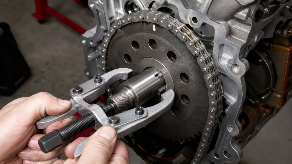
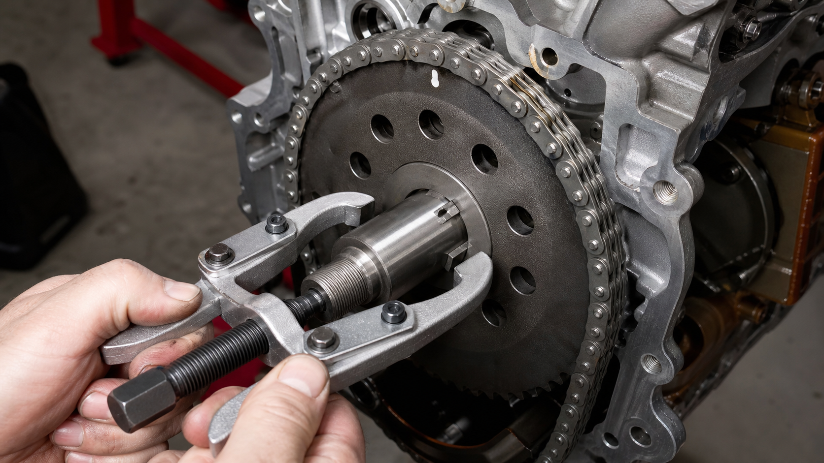
The crankshaft gear—also called the timing gear or crank sprocket—sits at the front of the crankshaft and drives the camshaft timing system. A single tooth off during installation shifts valve events enough to prevent startup or cause immediate piston-to-valve contact in interference engines. Loose fits, worn teeth, damaged keyways, and incorrect timing marks account for most field failures traced to this component. This article organizes inspection, removal, installation, and verification around the measurable changes that appear when the gear is loose, worn, mis-timed, or installed incorrectly.
Key Takeaways
- The crankshaft gear transfers rotation to the camshaft drive at a fixed ratio, typically 2:1 for four-stroke engines, and any timing error moves valve events relative to piston position.
- Interference fits and Woodruff keys secure the gear to the crankshaft nose; a loose fit allows the gear to walk forward or rotate independently under load.
- Tooth wear, keyway damage, and bore elongation are measurable with dial indicators, micrometers, and go/no-go gauges referenced to engine-maker drawings.
- Removal requires a dedicated puller to avoid shock loads that crack the crankshaft nose or damage the main bearing journal behind the gear.
- Timing-mark alignment and runout checks before startup prevent repeated failures and confirm that the gear is fully seated and correctly indexed.
Where the Crankshaft Gear Sits in the Timing Drive
The crankshaft gear mounts to the front end of the crankshaft, ahead of the front main bearing journal and behind the harmonic balancer or pulley. In most pushrod and overhead-cam engines, it meshes directly with an idler gear or drives a timing chain or belt sprocket. The gear’s rotational axis is the crankshaft centerline, and its radial position is controlled by an interference fit on the crankshaft nose diameter and a Woodruff key that indexes angular position.
The gear sits in a fixed relationship to crankshaft throw number one. When the number-one piston reaches top dead center on the compression stroke, the crankshaft gear timing mark must align with the corresponding mark on the camshaft gear or chain sprocket. This alignment sets valve opening and closing events relative to piston travel. A 2:1 drive ratio is standard for four-stroke engines: the crankshaft turns twice per camshaft revolution, so the crank gear typically has half the tooth count of the cam gear.
When the gear loosens on the taper or the keyway wears, the gear can rotate independently of the crankshaft during acceleration or deceleration. This creates a timing error that accumulates over multiple revolutions until valve-to-piston clearance is lost. The same loss of synchronization occurs if the gear is installed one tooth off, but in that case the error is immediate and fixed rather than progressive.
How the Gear Transfers Motion without Losing Timing Accuracy
Torque flows from the crankshaft into the gear through two parallel paths: friction at the interference fit and shear load on the Woodruff key. The interference fit creates a press force that clamps the gear hub to the crankshaft nose. This press fit alone can carry steady-state torque in low-output engines, but the key is required to handle transient torque spikes during startup and load changes.
The Woodruff key sits in a semicircular slot milled into the crankshaft nose and a matching keyway broached into the gear bore. The key is wider than it is tall, so it resists tilting and remains centered in the slot during installation. Torque applied to the crankshaft creates a shear load across the key cross-section. If the key is undersize, worn, or made from soft material, it will shear or deform, allowing the gear to slip relative to the crank.
Timing accuracy depends on zero relative motion between the gear and the crankshaft. An interference fit prevents axial and radial movement; the key prevents rotational slip. If the bore in the gear opens up from wear or heat cycling, the press fit is lost and the full torque load transfers to the key. The key then acts as a single-point pivot, concentrating stress at the key edges and accelerating keyway damage. Once the keyway is elongated, the gear can rock back and forth within the clearance, generating noise and further timing drift.
The gear teeth themselves must remain square to the gear axis and concentric with the bore. Runout exceeding the engine maker’s limit causes the chain or mesh point to move in and out once per revolution, creating tension spikes that wear the chain or opposing gear. Axial runout also changes the effective pressure angle at the tooth contact, accelerating tooth face wear. Consult the engine service manual for the specific runout tolerance applicable to your engine model.
Tooth Wear, Loose Fits, Keyway Damage, and Timing Errors
Tooth Wear Patterns and Measurement
Gear teeth wear asymmetrically when the load alternates between drive and coast. On the crankshaft gear, the drive side of each tooth shows more wear because combustion events apply positive torque most of the time. If one side of a tooth is polished smooth while the other side retains machining marks, the wear is still within normal limits. When the wear creates a visible step or radius at the tooth root, or when the tooth profile deviates from the involute curve by more than the drawing tolerance, the gear must be replaced.
Tooth thickness can be measured with gear tooth calipers at the pitch circle, or by using a ball or pin of known diameter and measuring over two teeth with an outside micrometer. The engine maker’s service manual will specify the minimum tooth thickness or the maximum allowable backlash when meshed with a new mating gear. Compare your measurements against these published specifications rather than general field limits, as acceptable wear varies significantly with gear design and loading conditions.
Loose Interference Fits
A loose gear will show axial movement when pried with a lever or tested with a feeler gauge at the back face. The gear should be tight enough that thin feeler blades cannot enter the gap between the gear face and the crankshaft shoulder. The engine manufacturer’s drawing specifies the interference fit on the diameter; measured interference below the minimum specification indicates the gear will not stay in place under operating torque.
The fit can be checked by measuring the bore of the gear and the outside diameter of the crankshaft nose with a micrometer or inside bore gauge. The difference should match the interference specification on the crankshaft drawing. A loose gear that has been running will show fretting wear—fine rust-colored powder—between the gear bore and the crank nose. This powder is oxidized metal abraded by micro-motion at the interface. The powder traps moisture and accelerates corrosion, further opening the bore. Once fretting starts, cleaning and re-pressing the same gear will not restore the fit; either the crankshaft nose must be built up and re-machined, or a new gear with an oversize bore must be fitted.
Keyway Damage and Elongation
The keyway in the crankshaft is more vulnerable than the key itself because the shaft material around the slot is interrupted and stress concentrates at the slot corners. Keyway damage appears as a radius or bevel at the slot edges, or as a crack radiating from the slot corner into the fillet between the nose and the first main journal.
Elongation can be measured by inserting the key into the slot and checking for lengthwise play. The key should fit with minimal clearance along its length according to the manufacturer’s specification. Excessive clearance indicates the slot has stretched and the gear will rattle during torque reversals.
A worn keyway cannot be repaired by welding and re-machining unless the crankshaft manufacturer’s repair manual explicitly permits it and specifies the welding procedure, preheat, interpass temperature, and post-weld heat treatment. Unauthorized weld repair in the keyway area creates residual tensile stress that nucleates fatigue cracks. The correct repair is to machine the nose to the next undersize diameter, fit an oversize key and keyway, and use a gear with a matching oversize bore.
Timing Errors from Installation Mistakes
A gear installed one tooth off will prevent the engine from starting or cause immediate damage in an interference design. The symptoms differ depending on the direction of the error. If the camshaft is advanced—rotated ahead of its correct position—the intake valve opens too early and the exhaust valve closes too late, reducing cylinder pressure during cranking. If the camshaft is retarded, the intake valve closes after bottom dead center and the exhaust valve opens before bottom dead center, again reducing compression.
The timing error can be confirmed by removing the valve cover and checking valve lash or rocker position at top dead center of the compression stroke for cylinder one. If both valves are closed and the rocker arms have the specified clearance, timing is correct within one tooth. If one valve is still open or the clearance is far from specification, the cam is mis-timed.
Timing marks on the gear must be referenced to the crankshaft keyway, not to an arbitrary tooth. Some gears have multiple timing marks for different engine variants or balancer-shaft configurations. Using the wrong mark will offset timing by two or more teeth. The engine service manual will identify the correct mark and its orientation relative to the keyway and to the mating gear or chain sprocket.
Removal and Installation without Damaging the Crank Nose
Removal with a Gear Puller
The interference fit requires a puller to extract the gear without hammering on the crankshaft. A two- or three-jaw puller hooks behind the gear face and pulls against the crankshaft nose. The puller jaws must contact the back face of the gear hub, not the teeth, to avoid bending the gear or breaking the jaws.
Before applying force, apply penetrating oil to the fit surface and let it soak. If the gear has been in place for extended service, heating the gear with a torch or induction heater will expand the bore and reduce the pull force. Avoid overheating; if the gear face discolors from oxidation, the material may have been softened and the gear should be replaced. Consult the manufacturer’s guidelines for acceptable heating temperatures.
Turn the puller screw gradually, alternating with light taps on the end of the crankshaft with a brass or lead hammer. The taps help break the static friction without shock-loading the crank nose. If the gear does not move after applying moderate force, recheck that the puller is square to the crank axis and that the jaws are fully seated behind the gear.
Installation Sequence
Clean the crankshaft nose and the gear bore with solvent to remove all oil, rust, and fretting residue. Measure the crank nose diameter and the gear bore to confirm the interference fit is within specification. If the bore is oversize or the nose is undersize, the gear will not stay in place even if pressed on fully.
Install the Woodruff key in the crankshaft slot and check that it sits below the nose diameter. If the key stands proud, it will prevent the gear from seating on the taper and will be crushed during installation, damaging both the key and the keyway.
Align the keyway in the gear with the key on the crank and slide the gear onto the nose by hand until it contacts the taper. Do not force it; if the gear stops before reaching the taper, the keyway is misaligned. Heating the gear will expand the bore enough to slip over the key without force. Follow the manufacturer’s recommended heating method and temperature range.
Press or drive the gear onto the taper using a sleeve or socket that contacts the gear hub, not the teeth or the outer rim. Apply steady pressure with a hydraulic press or drive the gear with a soft-face hammer, moving around the circumference to keep the gear square to the crank axis. The gear is fully seated when its back face contacts the crankshaft shoulder and no thin feeler gauge can enter the gap.
Do not press the gear by forcing the installation bolt or nut against the gear face. This method generates a shock wave through the crankshaft every time the threads bottom out, and the shock can crack the fillet between the nose and the first main journal. If a press is not available, a gear installer tool with a threaded rod and reaction plate distributes the load more evenly than a hammer.
Timing and Fit Verification before Startup
Timing-Mark Alignment
After installation, rotate the crankshaft by hand to bring cylinder one to top dead center on the compression stroke. Both valves should be closed and the piston should be at its highest position. Align the timing mark on the crankshaft gear with the mark on the camshaft gear or chain sprocket according to the engine service manual. The marks may be dots, lines, or stamped numbers. If the marks do not align within the acceptable tolerance specified by the manufacturer, remove the camshaft gear or chain and re-index it.
On chain-driven systems, ensure the chain is routed correctly and has the specified tension. A loose chain will allow the cam timing to wander under load, and an overly tight chain will overload the chain tensioner and accelerate wear. Chain tension is typically checked by measuring deflection at the mid-span between the crank and cam sprockets with a specified force applied perpendicular to the chain. Refer to the service manual for the correct tension specification and measurement procedure.
Runout and Axial Play Checks
Mount a dial indicator with its plunger contacting the front face of the gear near the outer diameter. Rotate the crankshaft one full turn and record the total indicator reading. Compare axial runout against the manufacturer’s specification. If runout is excessive, the gear is cocked on the taper or the nose taper itself is not concentric with the main journal.
Repeat the measurement with the indicator plunger contacting the tooth face at the pitch circle. Compare radial runout against the service manual limit. High radial runout indicates a bent gear or a bent crankshaft nose.
Check axial play by attempting to pry the gear away from the shoulder with a lever. Movement exceeding the manufacturer’s tolerance indicates the gear is not fully seated or the shoulder has worn.
Functional Test Sequence
Before starting the engine, bar it over by hand for two complete revolutions to confirm that no valve-to-piston interference exists and that the starter ring gear or flexplate turns freely. Listen for unusual rubbing or clicking sounds as the crank rotates; any noise from the timing area suggests a loose gear or misaligned chain.
Start the engine and let it idle. A correctly installed crankshaft gear produces no noise distinct from normal valvetrain clatter. If a knocking or rattling sound originates from the front cover, shut down immediately and re-inspect the timing marks, chain tension, and gear fit.
Monitor oil pressure during the first few minutes of operation. A sudden drop in pressure after the gear is installed may indicate that the gear has walked forward on the taper and partially blocked the oil passage feeding the front main bearing. This failure mode is rare but catastrophic; if pressure does not stabilize quickly after startup, stop the engine and remove the front cover to inspect the gear position.
FAQs
Can a crankshaft gear be reused after removal?
Reuse depends on the measured condition of the bore and the teeth. If the bore has not opened beyond the minimum interference specification, the teeth are within thickness limits, and no cracks or fretting are visible, the gear can be reinstalled. Gears that have been heated excessively during removal should be replaced because the heat treatment may have been compromised. Consult the manufacturer’s reuse guidelines and compare your measurements against the published specifications.
What causes a new crankshaft gear to fail within the first hundred hours?
Early failures are usually caused by incorrect installation: inadequate press fit, wrong timing marks, damaged key, or a cocked gear creating runout. Another common cause is contamination between the bore and the crankshaft nose—oil, dirt, or rust prevents the gear from seating fully, leaving it loose enough to fret and wear the bore within a short period of operation.
How do I identify the correct replacement gear when the original part number is obsolete?
Measure the crankshaft nose diameter, the distance from the nose shoulder to the front face of the gear, the gear bore, the tooth count, the outside diameter, and the keyway width. Cross-reference these dimensions with the engine service manual or a parts supplier catalog. If no direct replacement is available, a crankshaft manufacturer can machine a custom gear to match the measured geometry and the mating cam gear.
Is it acceptable to use a gear from a different engine model if the tooth count and bore diameter match?
Not without verifying the hub length, keyway position, timing-mark location, and tooth pitch. Two gears with the same tooth count may have different diametral pitch or pressure angle, making them incompatible with the existing cam gear or chain. The hub length must also match to avoid interference with the front cover or harmonic balancer. Always cross-reference critical dimensions against the engine manufacturer’s specifications before substituting parts.
What is the maximum allowable backlash between the crankshaft gear and the idler or cam gear?
Backlash limits vary by engine design and gear size. Excessive backlash allows the gears to hammer against each other during torque reversals, accelerating wear. Insufficient backlash causes binding and overheating. The engine service manual provides the correct specification for your specific model. If the manual is unavailable, measure backlash on a known-good assembly of the same model for comparison.
Conclusion
Crankshaft gear integrity depends on correct fitment, accurate timing-mark alignment, and verification that the interference fit and keyway remain within tolerance. When wear, damage, or incorrect installation compromise these conditions, timing errors and mechanical failures follow quickly. Measure bore diameter, tooth thickness, keyway clearance, and runout against the engine-maker specification before deciding whether to reuse or replace the gear. Use a puller during removal and a press or drift during installation to avoid shock loads that crack the crankshaft nose. Confirm timing alignment and minimal axial play before startup, and monitor oil pressure and front-end noise during the first operating cycle. For custom or obsolete gears, consult the crankshaft drawing and verify material, heat treatment, and tooth geometry through a qualified crankshaft manufacturer before ordering.