
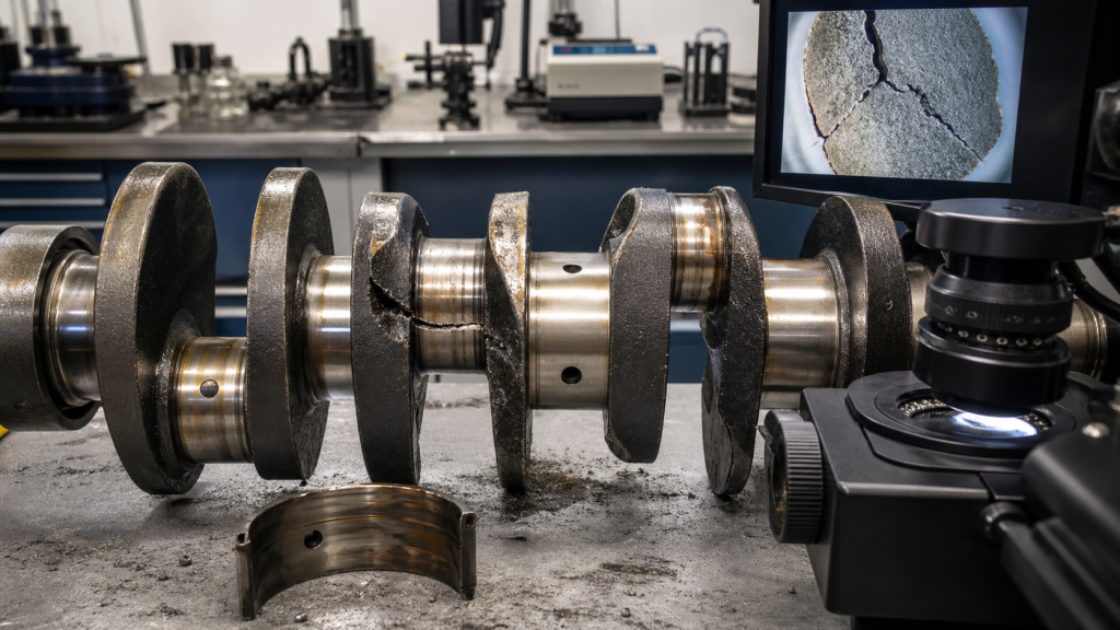
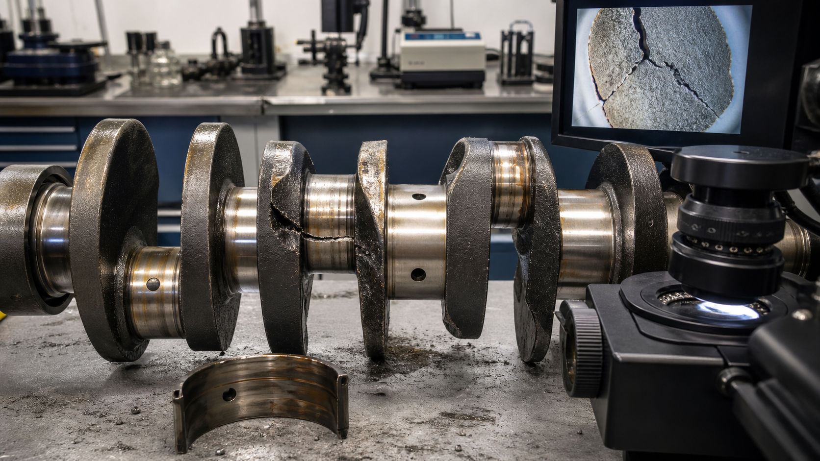
A broken crankshaft leaves behind a trail of evidence. The fracture surface, bearing condition, journal geometry, and oil-passage state reveal whether failure began with lubrication loss, fatigue, bending overload, or assembly error. Crankshaft failure stops production, damages engine blocks, and triggers expensive teardowns—yet the root cause is often visible on the shaft itself if inspectors read the failure surface before cleaning, grinding, or discarding the evidence. This article walks through the mechanisms, warning signs, and inspection logic that prevent guesswork and repeated failures in diesel, truck, and automotive engines.
Key Takeaways
- Fracture appearance, location, and propagation direction identify whether failure began with fatigue, bending, lubrication loss, or torsional overload.
- Lubrication loss creates bearing-journal seizure, scoring, and thermal cracks before final fracture; oil-passage inspection confirms or rules out blockage.
- Bending failures show plastic deformation at main or rod journals when misalignment, harmonic balancer loss, or abnormal combustion loads exceed the shaft’s yield strength.
- Fatigue cracks nucleate at fillet radii, press-fit transitions, or oil-hole edges when stress concentration combines with cyclic loading and surface defects.
- Runout, journal diameter, fillet radius, and oil-passage diameter measurements separate normal wear from geometry changes that demand replacement.
- Root-cause inspection of engine block bearing bores, crankcase alignment, flywheel/damper condition, and timing components prevents installing a new crankshaft into the same failure environment.
Read the Failure Surface before Cleaning Away the Evidence
A fractured crankshaft presents three distinct surface textures. A fatigue fracture begins at a stress riser—fillet radius, oil-hole edge, or press-fit boundary—and propagates slowly through alternating tension and compression cycles. The fracture surface shows concentric beach marks radiating from the initiation site, with fine-grained texture in the fatigue zone and coarse, fibrous tearing in the final overload region. A bending overload fracture shows little or no fatigue progression; the shaft yields plastically at the journal, then tears across the entire cross-section with visible necking on the tension side. A thermal fracture from lubrication loss displays oxidation, temper colors, or intergranular separation near the bearing surface, often accompanied by scoring and metal transfer on the journal.
Preserve the fracture surface during disassembly. Cleaning solvents, wire brushing, or ultrasonic baths erase beach marks, oxide colors, and deposit patterns that locate the crack origin. Photograph both fracture faces under oblique lighting before handling. Mark the orientation—top dead center, firing order, and cylinder position—so that stress analysis can correlate the fracture location with peak cylinder pressure, torsional mode shape, or main-bearing load distribution.
Measure the crack length along the fracture perimeter to estimate how many cycles the shaft operated after crack initiation. A crack that consumed most of the cross-section before final fracture indicates gradual fatigue, while a small crack suggests rapid overload after minimal fatigue life. Compare the fracture location against the original heat treatment zone boundaries—nitrided case depth, induction-hardened pattern, or fillet-rolled compression layer—to confirm whether surface hardening was applied and retained.
Lubrication Loss and Bearing-Origin Damage
Bearing failure generates the majority of secondary crankshaft damage. When oil pressure drops below the minimum film thickness for hydrodynamic lubrication, metal-to-metal contact occurs at the bearing-journal interface. The journal surface temperature rises above the tempering point of the hardened case, softening the material and allowing abrasive wear. Bearing material—aluminum, copper-lead, or babbitt—transfers onto the journal, creating built-up deposits that score both surfaces. Thermal cracks nucleate perpendicular to the journal axis as local heating and cooling cycles create residual tension in the surface layer.
Inspect all main and rod journals for scoring depth, material transfer, and discoloration. Use a micrometer to measure journal diameter at 90° intervals and compare against the engine manufacturer’s standard diameter and repair undersize limits. Deep scoring typically requires regrinding to the next undersize; severe scoring may penetrate the hardened case and expose softer core material. Consult the engine maker’s repair manual for rejection criteria. Check the oil passages with a wire gauge or borescope. Sludge, casting flash, or debris blockage in the main-journal feed holes starves downstream rod bearings even when the oil pump delivers full pressure at the gallery.
Examine bearing shells for wiping patterns, which indicate the load zone and oil-film breakdown region. A bearing with uniform wear across its full contact arc operated with adequate lubrication; a bearing with localized wiping, scoring, or copper showing through the overlay in a narrow band suffered oil starvation or misalignment. Measure bearing clearance with Plastigage or inside micrometers. Clearance exceeding the engine maker’s maximum limit allows oil flow to bypass the bearing rather than building pressure film, creating a self-reinforcing wear loop that ends in journal seizure.
Oil analysis from the failed engine often shows elevated iron, copper, lead, and aluminum, confirming bearing and journal wear. Silicon or dirt contamination points to air-filter failure or inadequate oil filtration. Fuel dilution lowers oil viscosity and film strength, reducing load capacity at the bearing-journal interface. Cross-reference oil-analysis trends with maintenance records to determine whether failure resulted from neglected oil changes, wrong-viscosity oil, or a sudden loss-of-pressure event such as pump failure or pickup-screen blockage.
Bending, Misalignment, and Abnormal Combustion Loads
Crankshaft bending occurs when applied loads exceed the shaft’s yield strength in a single event or when misalignment creates uneven bearing reactions. Inspect the main journals for runout by mounting the shaft in V-blocks or between lathe centers and rotating it under a dial indicator. Runout greater than the engine maker’s limit indicates permanent bending. Measure runout at each main journal and at the flange face; the pattern reveals whether bending occurred at a single journal, across multiple mains, or at the flywheel attachment. Refer to the engine manufacturer’s service manual for specific runout tolerances.
Bending failures often initiate at the main journal nearest the failed cylinder or at the front main where the harmonic balancer or drive pulley attaches. A loose or failed harmonic balancer removes torsional damping and allows large torsional amplitude at the natural frequency of the crankshaft, generating alternating bending stress at the front main journal. A hydrolocked cylinder from water ingestion or fuel accumulation creates a sudden compression load far exceeding normal peak cylinder pressure, bending the rod journal and transmitting the overload to adjacent main journals. A spun bearing shifts the load path and introduces a moment arm that bends the shaft.
Check main-bearing bore alignment in the engine block before installing a replacement crankshaft. Use a precision straightedge or dedicated boring bar to measure bore-to-bore centerline alignment and bore diameter. Misalignment beyond the manufacturer’s tolerance creates uneven bearing loading and side forces that bend the crankshaft under normal operation. Worn or damaged bearing caps, uneven cap-bolt torque, or block distortion from overheating all introduce misalignment. Line-boring or line-honing the block restores alignment, but requires reducing bearing-bore diameter and installing oversize bearing shells.
Measure rod journal diameter, taper, and ovality. Excessive taper indicates uneven loading from connecting-rod misalignment, piston scuffing, or bent rod. Excessive ovality shows that journal deformation began before final fracture. Compare these measurements against the engine maker’s wear limits and regrind specifications to determine whether the shaft can be restored to the next undersize or must be replaced.
Torsional Vibration and Fatigue Cracks
Torsional vibration generates alternating shear stress in the crankshaft, with peak amplitude at the shaft’s natural frequency. Diesel and high-output gasoline engines operate across a wide speed range, and certain rpm values align the firing frequency with the crankshaft torsional mode, creating resonance. A properly sized harmonic balancer or dual-mass flywheel damps torsional amplitude at the critical speed, but a failed damper, incorrect balancer, or missing flywheel allows unchecked vibration and fatigue crack initiation.
Fatigue cracks nucleate at stress concentrations: fillet radii between journals and crank webs, oil-hole edges, keyways, and press-fit transitions. Forged crankshafts with rolled fillets have higher fatigue strength than cast or machined shafts because fillet rolling induces compressive residual stress that opposes crack opening. Inspect fillet radii with magnetic-particle or dye-penetrant testing after removing the shaft from the engine. Surface cracks appear as linear indications radiating from the high-stress region of the fillet. Subsurface cracks may not be visible until the shaft fractures, so nondestructive testing should be performed at scheduled intervals on high-hour or high-output engines.
Measure fillet radius with a radius gauge. A fillet radius below the drawing minimum increases stress concentration and reduces fatigue life. Grinding, polishing, or peening during remanufacturing can alter the fillet profile; confirm that machined fillets match the original rolled or cast contour. Stress concentration at oil holes can be reduced by chamfering or radiusing the hole entrance, but any modification must be approved by the engine maker or engineering analysis to avoid introducing new failure modes.
Check the harmonic balancer or damper for rubber deterioration, inertia-ring separation, or hub slippage. A failed damper allows the front of the crankshaft to oscillate at large torsional amplitude, concentrating fatigue damage at the first main journal or front rod journal. Replace the damper during every crankshaft replacement unless the engine maker specifies a longer service interval with verified damper condition.
Warning Signs: Knock, Vibration, Oil Pressure, and Metal Debris
A failing crankshaft generates several observable symptoms, but none are exclusive to crankshaft damage. A low-frequency knock synchronized with crankshaft rotation indicates main-bearing clearance or crankshaft runout, but the same knock can come from a worn rod bearing, loose flywheel, or failed harmonic balancer. Excessive engine vibration at idle or under load suggests crankshaft imbalance, bending, or missing counterweight, but can also result from engine-mount failure, flywheel runout, or misfiring cylinders. Low oil pressure may indicate bearing clearance exceeding limits, but also results from oil-pump wear, pressure-relief-valve failure, or restricted oil passages in the block.
Check the oil filter and drain plug for metal debris. Aluminum particles indicate bearing wear; steel or iron particles suggest journal scoring, gear wear, or camshaft damage; copper or brass flakes point to bushing or thrust-washer failure. Send an oil sample for spectroscopic analysis to quantify wear metals and compare against baseline or trend data. A sudden increase in iron concentration confirms journal or bearing wear in progress.
Monitor oil pressure with a mechanical gauge, not the dashboard warning light. Compare running pressure against the engine maker’s specification at idle and at rated speed. Pressure below specification at idle with normal pressure at speed indicates excessive bearing clearance; pressure below specification at all speeds suggests pump failure or blocked passages. If pressure remains in specification but the engine shows other symptoms, bearing clearance may still be at the high end of tolerance, and journal taper or ovality may be present.
Inspect the crankcase breather and PCV system for excessive blow-by. Combustion gases escaping past worn piston rings pressurize the crankcase and force oil past seals, but a cracked crankshaft web or failed crankcase gasket also allows pressure loss and oil leakage. Compression and leak-down testing isolates cylinder sealing problems from crankshaft or bearing issues.
Root-Cause Inspection before Installing Another Crankshaft
Installing a replacement crankshaft without addressing the root cause reproduces the failure. Perform a complete inspection of the engine block, connecting rods, and driven components before ordering or installing a new shaft.
Engine Block and Bearing Bores
Measure main-bearing bore diameter, centerline alignment, and surface finish. Line-bore or line-hone the block if bore alignment exceeds tolerance or if bearing bores show fretting, galling, or distortion. Check bearing-cap bolt threads and seating surfaces; damaged threads or uneven cap contact introduce misalignment. Torque all main caps to specification using a calibrated torque wrench and the engine maker’s tightening sequence. Inspect the crankcase for cracks, especially around main-bearing webs and oil-gallery plugs.
Connecting Rods and Rod Bearings
Measure connecting-rod big-end bore diameter, perpendicularity to the rod centerline, and small-end bushing condition. A bent or twisted rod creates side loading that bends the crankshaft and concentrates bearing wear in a narrow zone. Recondition or replace rods that exceed the engine maker’s straightness or bore tolerance. Check rod bolts for necking, thread damage, or stretch beyond reuse limits; replace rod bolts during every crankshaft replacement in high-output or high-hour engines.
Harmonic Balancer, Flywheel, and Drive Components
Inspect the harmonic balancer for rubber deterioration, hub cracks, or inertia-ring separation. Replace the balancer if it shows any damage or if service hours exceed the manufacturer’s recommended interval. Measure flywheel runout and pilot-bearing bore diameter. Excessive flywheel runout creates imbalance and torsional excitation. Check the front pulley, drive belt, and any gear or chain drives for wear or misalignment.
Lubrication System and Oil Quality
Replace the oil pump if bearing clearance measurements indicate loss of pressure. Inspect the oil-pump pickup screen for debris or cracks. Clean all oil galleries in the block and verify that gallery plugs are sealed and torqued. Flush the cooling system and check the oil cooler for internal leaks that allow coolant into the oil. Use the oil grade and viscosity specified by the engine maker; aftermarket or racing oils may lack the additive package required for diesel or forced-induction applications.
Crankshaft Selection and Verification
Obtain the engine model, serial number, and any applicable revision or build code from the engine nameplate. Cross-reference these identifiers against the engine maker’s parts catalog or service manual to identify the correct crankshaft part number, material specification, and balancing requirements. Forged crankshafts offer higher fatigue strength than cast shafts and are preferred for high-output, heavy-duty, or racing applications; cast crankshafts are cost-effective for stock-replacement and moderate-duty engines. Learn more about how crankshafts are manufactured and automobile crankshaft production.
Request material certification, dimensional inspection reports, and balancing records from the crankshaft supplier. Verify that main and rod journal diameters, fillet radii, oil-hole locations, and overall length match the engine maker’s drawing. If the replacement shaft will be installed with new bearings, confirm bearing shell part numbers and installed clearance limits. If the block was line-bored or if oversized bearings will be used, specify the required journal undersize and balancing target.
For custom or modified engines, provide the engine builder or machine shop with complete specifications: stroke, rod length, piston compression height, bobweight, and target balance factor. A crankshaft balanced for the wrong bobweight creates vibration and accelerates bearing wear.
FAQs
Can a crankshaft be repaired or must it always be replaced?
Minor scoring and journal wear can be corrected by grinding to the next standard undersize specified by the engine manufacturer. Common undersize increments are defined in the engine maker’s service manual. Grinding removes damaged material and restores the journal to a precision diameter with proper surface finish. The shaft must retain sufficient hardness after grinding; if grinding penetrates the hardened case, the journal will wear rapidly. Fatigue cracks, bending beyond tolerance, or damage to thrust surfaces, keyways, or threads usually make the shaft uneconomical to repair. Consult the engine maker’s repair manual for allowable undersizes and rejection criteria. For more guidance, see the crankshaft repair decision guide.
How often should crankshaft inspection be performed in high-hour engines?
Inspection intervals depend on engine duty cycle, operating environment, and manufacturer recommendations. Heavy-duty diesel engines in continuous service—marine, industrial, or power generation—follow the engine maker’s specified overhaul intervals. High-performance or racing engines may require inspection after every event or at frequent service intervals. Routine oil analysis, bearing inspection during oil changes, and vibration monitoring provide early warning of developing problems and may extend inspection intervals in well-maintained engines. Always follow the engine manufacturer’s maintenance schedule.
What causes crankshaft failure shortly after installation of a new or reground shaft?
Repeated failure indicates that the root cause was not corrected. Common causes include: main-bearing bore misalignment in the block, incorrect bearing clearance, reused or damaged rod bolts, failed harmonic balancer, contaminated oil supply, incorrect oil viscosity, loose flywheel or drive pulley, and improperly torqued or damaged bearing caps. Always verify block alignment, replace wear components, and confirm that the lubrication system delivers adequate pressure and clean oil before blaming the replacement crankshaft.
Can a bent crankshaft be straightened?
Straightening is sometimes attempted by heating the bent section and applying controlled force in a press or by peening the compression side of the bend. This process is difficult to control, risks introducing new residual stresses, and may crack the shaft if heating alters the microstructure. Straightening is generally not recommended for hardened or nitrided crankshafts because heat destroys the surface treatment. Replacement is more reliable than straightening for production engines.
How do I determine if a used or salvage crankshaft is acceptable for reuse?
Measure all main and rod journal diameters, runout, fillet radii, and oil-passage diameter. Compare measurements against the engine maker’s standard, wear limits, and minimum regrind sizes. Perform magnetic-particle or dye-penetrant inspection to detect cracks. Check for rust, pitting, or corrosion in oil passages and on thrust surfaces. Verify that the part number and stroke match the target engine. A crankshaft from a failed or unknown-history engine should be treated as suspect and inspected to the same standard as a new shaft.
Conclusion
Crankshaft failure follows a measurable sequence: crack initiation at a stress concentration, propagation through cyclic loading, and final fracture when the remaining cross-section cannot support peak loads. The fracture surface, bearing condition, journal geometry, and block alignment reveal whether failure originated from lubrication loss, fatigue, bending, or assembly error. Prevention requires matching the crankshaft material, heat treatment, and geometry to the engine’s load profile, maintaining oil pressure and cleanliness, replacing wear components on schedule, and verifying that the engine block, rods, and driven components remain within tolerance. Before ordering a replacement shaft, obtain the engine model and serial number, measure bearing bores and runout, inspect the harmonic balancer and flywheel, and request dimensional certification and material test reports from the supplier.