
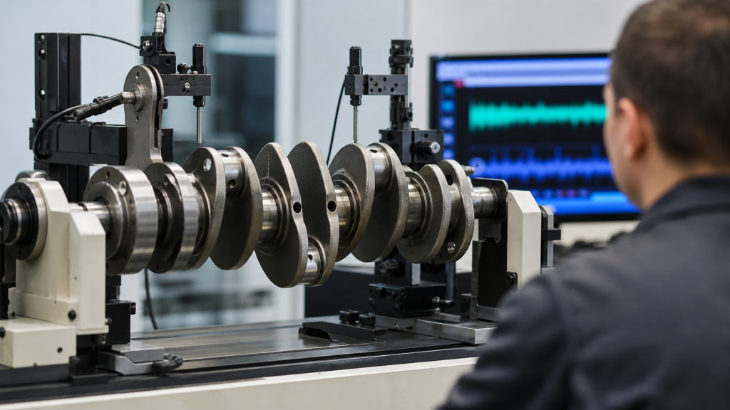
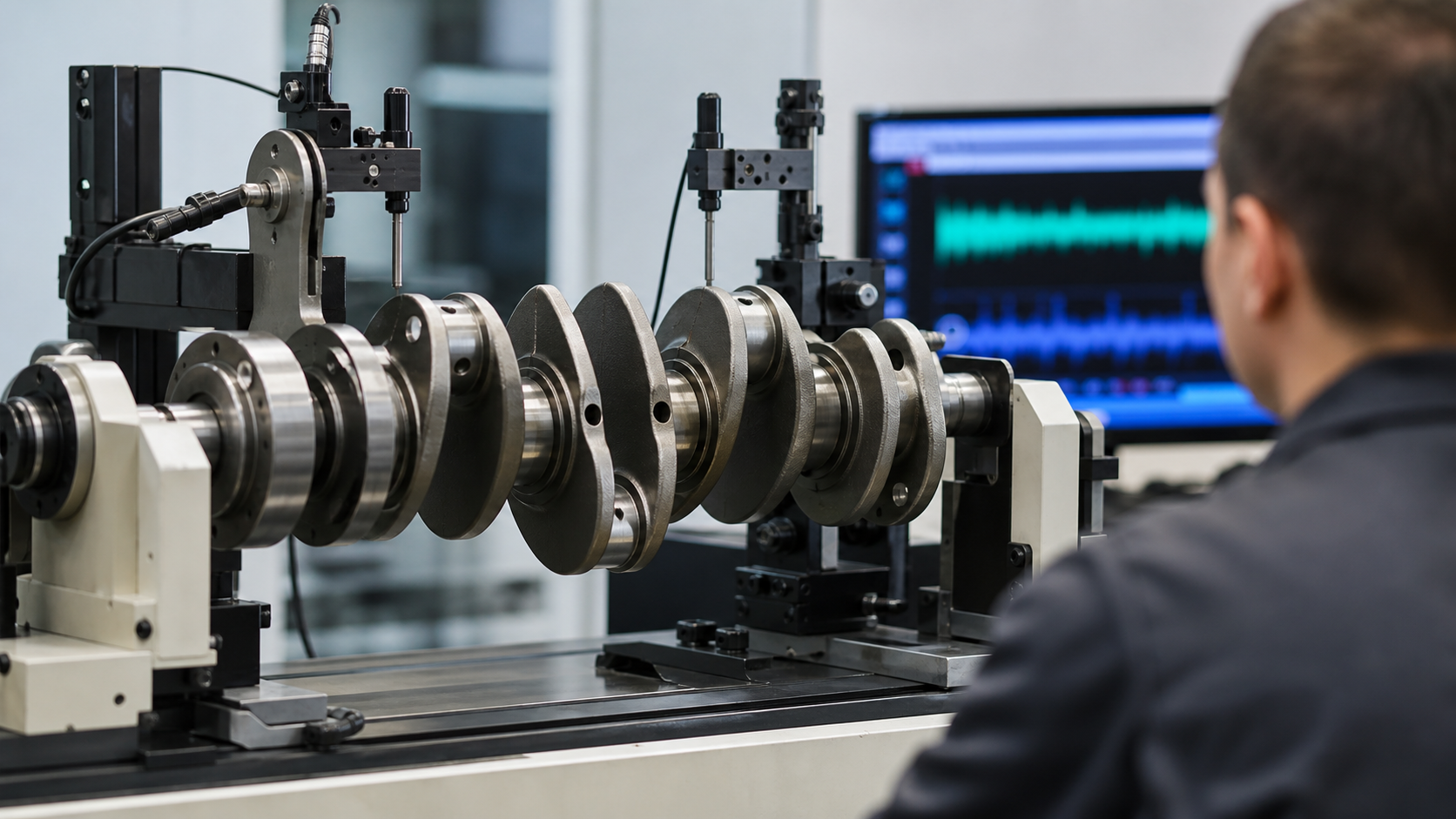
A machined crankshaft can pass runout inspection, sit perfectly level on V-blocks, and still produce destructive vibration the moment it spins under load. The problem is not alignment or bearing clearance—it is mass distribution. Crankshaft balancing corrects the uneven forces created when offset journals, counterweights, and reciprocating components accelerate and decelerate thousands of times per minute. Without balance correction, these forces generate vibration that fatigues main bearings, cracks castings, and shortens engine life.
Balancing addresses two distinct mass systems: the rotating assembly (crankshaft journals, counterweights, and a portion of the connecting rods) and the reciprocating assembly (pistons, pins, rings, and the remaining rod mass). Because the crankshaft cannot be balanced in isolation from the components it drives, machine shops use calculated bobweights to simulate the combined inertia during the balancing operation. This article explains how static and dynamic balancing differ, how counterweights are corrected through drilling or welding, and which changes to the rotating assembly require rebalancing.
Key Takeaways
- A straight crankshaft can still generate destructive vibration if rotating and reciprocating masses are not properly distributed around the axis of rotation.
- Static balance addresses forces in a single plane; dynamic balance corrects forces and moments across two or more planes, which is required for multi-throw crankshafts.
- Bobweights simulate the combined mass and inertia of pistons, rods, rings, and pins during the balancing operation, using percentages defined by the engine manufacturer.
- Counterweight correction is performed by drilling to remove material or by welding heavy-metal plugs into existing holes when additional mass is needed.
- Grinding journals, changing pistons or rods, or installing a different damper or flywheel all alter the rotating assembly and typically require rebalancing.
- A balance report should document bobweight calculation, correction plane locations, material removed or added, and final residual imbalance in gram-millimeters per plane.
A Straight Crankshaft Can Still Be Out of Balance
Runout measurement verifies that main and rod journals are concentric and that the crankshaft will rotate without eccentric wobble in the bearings. It does not measure how mass is distributed relative to the centerline. If one counterweight is heavier than its opposite, or if a rod journal has an oil passage drilled off-center, the imbalance creates a rotating force vector that changes direction with crankshaft rotation. At operating speed, this force generates vibration transmitted through the main bearings into the block, mounts, and frame.
The force magnitude follows the equation:
F = m × r × ω²
where F is centrifugal force (Newtons), m is the imbalanced mass (kilograms), r is the radial distance from the rotation axis (meters), and ω is angular velocity (radians per second). Because force increases with the square of speed, a small imbalance tolerable at idle becomes destructive at rated RPM. To illustrate: assuming a 10-gram imbalance at 50 mm radius, the calculation produces approximately 14 Newtons at 1,000 RPM but 1,400 Newtons at 10,000 RPM. This quadratic relationship explains why high-speed engines require tighter balance tolerances than low-speed industrial or marine diesels.
Balance limits are specified by the engine manufacturer and expressed in gram-millimeters (g·mm) or ounce-inches. The limit accounts for crankshaft mass, journal diameter, operating speed range, bearing type, and acceptable vibration at the mounting points. Heavy-duty engines operating at lower speeds may permit larger residual imbalance values, while racing engines demand much tighter limits. Using a generic tolerance without reference to the specific engine specification risks either unnecessary rework or insufficient correction.
Rotating Mass, Reciprocating Mass, and the Bobweight Model
The crankshaft rotates continuously, but the pistons, pins, and rods reciprocate—they stop, reverse direction, and accelerate twice per revolution. Because the connecting rod moves in a complex path, part of its mass behaves as rotating mass (the big end) and part as reciprocating mass (the small end). The typical split assigns 100% of the piston, pin, rings, and locks as reciprocating, and divides the rod mass based on the distance from the small-end center of gravity to the big-end center of gravity. A common approximation is 60% reciprocating and 40% rotating, but the actual percentages must come from the engine manufacturer’s balancing specification or be measured directly by suspending the rod on a knife edge.
Bobweights are temporary masses clamped to each rod journal during the balancing operation to simulate the combined inertia of the piston assembly and the rotating portion of the rod. The bobweight calculation follows this form:
Bobweight = (Piston + Pin + Rings + Locks) + (Rod rotating %) + (Rod bearing + Bolts)
For example, if the piston assembly weighs 450 grams, the rod weighs 600 grams with a 40% rotating factor, and the bearing and hardware add 80 grams, the bobweight is 450 + 240 + 80 = 770 grams. Each rod journal receives an identical bobweight to simulate a complete cylinder assembly. The crankshaft with bobweights installed is then corrected to achieve the target residual imbalance.
The bobweight model assumes that all pistons, pins, and rods are matched to within close tolerance. If components vary significantly, the balance operation will reflect an average that may not suit any individual cylinder. Best practice weighs each piston and rod, sorts them into matched sets, and assigns the heaviest components to cylinders with the smallest counterweights to minimize the range of correction required. For crankshaft manufacturing operations producing high-volume engines, component tolerances are controlled during production to ensure consistent bobweight targets across the entire engine family.
Static Balance vs Two-Plane Dynamic Balance
Static balance measures whether the crankshaft’s center of mass lies on the axis of rotation. A statically balanced crankshaft will not roll when placed on parallel knife edges or rails—it remains at rest in any position because there is no net force pulling one side down. Static balance is sufficient for components that are thin relative to their diameter, such as flywheels, clutch discs, or single-throw crankshafts where all journals lie in the same transverse plane.
Multi-throw crankshafts require dynamic balance because the throws are spaced along the length of the shaft. Even if the crankshaft is statically balanced, unequal mass distribution at different axial positions creates a rocking couple (moment) when the shaft spins. This moment cannot be detected by static knife-edge methods but generates significant vibration at operating speed. Dynamic balancing measures imbalance in at least two correction planes, typically near the front and rear main journals, and corrects both the force vector and the moment.
A dynamic balancing machine spins the crankshaft on soft-mounted bearings and uses vibration sensors or optical encoders to measure the amplitude and phase of imbalance in each plane. The machine calculates how much material to remove (or add) at which angular position in each plane to bring residual imbalance within specification. For inline four-cylinder and V8 configurations, balancing is typically performed in two planes. Inline six-cylinder crankshafts may require correction in three or more planes depending on length and bearing span.
Some engines use external balancing, where part of the correction mass is placed on the harmonic damper or flywheel rather than entirely within the crankshaft counterweights. This approach reduces the machining required on the crankshaft and allows correction after journal grinding or other modifications. External balance components must be marked and installed in the correct orientation; interchanging a neutral-balance damper onto an externally balanced crankshaft will reintroduce the original imbalance.
How Material Is Corrected at the Counterweights
Once the balancing machine identifies the location and magnitude of imbalance in each correction plane, material is added or removed from the counterweights to shift the center of mass back onto the rotation axis. Material removal is the more common operation and is performed by drilling holes into the counterweights at the angular positions indicated by the machine. The depth and diameter of the holes are calculated to remove the exact mass required without weakening the counterweight structure or intersecting oil passages.
For cast-iron crankshafts, drilling is typically the only correction method used, because the material is less expensive and counterweights are sized with enough mass to allow removal. Forged-steel crankshafts may be designed with pre-drilled lightening holes that can be enlarged during balancing, or with solid counterweights that allow drilling at any position. Fillet-rolled crankshafts require care to avoid drilling into the fillet radius zone, where stress concentration could initiate a fatigue crack.
When a counterweight requires additional mass, heavy-metal plugs are pressed or welded into existing holes. Mallory metal—a tungsten alloy with density around 18 g/cm³ compared to 7.8 g/cm³ for steel—allows significant mass addition in a small volume. The plug is typically secured by interference fit, staking, or welding, and must remain in place under centrifugal load and thermal cycling. Heavy-metal correction is most common after journal grinding, which removes material from the crankshaft and shifts the balance toward the counterweight side, or when switching to lighter pistons or rods that reduce the required bobweight.
The balance report should document which counterweights were corrected, the angular position and depth of each hole, and the mass of any heavy-metal plugs installed. This record allows a rebuilder to verify that previous balance work is still valid, or to calculate the correction required if components are changed again.
When Grinding, Pistons, Rods, or Dampers Require Rebalancing
Any operation that changes the mass or mass distribution of the rotating assembly requires rebalancing. Grinding main or rod journals to restore bearing clearance after wear or damage removes material from the crankshaft, which shifts the center of mass toward the counterweights. As an illustration: a 0.25 mm (0.010 inch) undersize grind on a 60 mm diameter journal removes approximately 5 grams per journal. Across six rod journals, this totals 30 grams moved radially outward by 30 mm, equivalent to 900 g·mm of imbalance—well beyond acceptable limits for most engines. The balance shop must recalculate bobweights if pistons, pins, rods, or bearings are changed, even if the crankshaft itself is not machined.
Replacing a harmonic damper or flywheel also affects balance when the original components were part of an external-balance design. Some V8 engines, for example, use an offset weight cast into the damper hub to counteract imbalance intentionally left in the crankshaft. Installing a neutral-balance damper on such an engine reintroduces the full crankshaft imbalance. Conversely, installing an externally balanced damper on a crankshaft that was internally balanced adds an unnecessary imbalance. Dampers and flywheels must match the crankshaft’s balance strategy, and this information should be verified against the engine manufacturer’s parts catalog or service manual before assembly.
Stroker kits, which increase stroke by using longer-throw crankshafts, typically require custom balancing because the increased journal offset and longer rods change both rotating and reciprocating mass. The counterweights may need to be enlarged or welded with heavy metal to accommodate the increased bobweight. For billet crankshaft designs, counterweights are often machined oversize initially and then corrected to final balance during the finishing operation, allowing flexibility for different piston and rod combinations.
Rebalancing after repairs follows the same procedure as initial balancing: weigh all rotating and reciprocating components, calculate bobweights per the engine specification, install bobweights on the crankshaft, spin the assembly in a dynamic balancing machine, and correct the counterweights until residual imbalance is within tolerance in all planes.
Balance Report Details to Confirm
A complete balance report serves as both a process record and a specification for reassembly. It should include component weights, bobweight calculation, machine settings, correction details, and final results. Minimum documentation includes:
- Component weights: individual masses for pistons, pins, rings, locks, rods (total and separated into rotating and reciprocating portions), rod bearings, and hardware. These values allow verification that components were measured rather than assumed, and provide a reference if components are substituted later.
- Bobweight formula and result: the calculation method and percentage split applied to the connecting rods, and the total bobweight installed on each rod journal. This value must match the engine manufacturer’s specification or the measured rod characteristics.
- Correction plane locations: the axial position and angular reference (typically relative to the number-one rod journal or a timing mark) for each balance plane. Multi-throw crankshafts usually require two planes, but longer shafts may use three or more.
- Material removed or added: the location, angular position, diameter, and depth of drilled holes, or the mass and position of heavy-metal plugs. This data allows a subsequent rebuilder to assess whether additional correction is possible or whether the counterweights are at their structural limit.
- Residual imbalance per plane: the final measured imbalance in each correction plane, expressed in gram-millimeters or ounce-inches. This value must be at or below the engine manufacturer’s limit. If no manufacturer limit is available, ISO 1940-1 provides general guidance based on crankshaft mass and operating speed, but engine-specific limits are always preferred.
- Machine calibration and reference standard: notation that the balancing machine was verified against a known-good reference weight before the job. This proves traceability and reduces the risk of systematic error.
For replacement crankshafts ordered from a crankshaft manufacturer, the purchase specification should state whether the part is supplied neutral-balanced (suitable for any piston and rod combination with rebalancing), internally balanced to a stated bobweight, or externally balanced with specified damper and flywheel requirements. Supplying the complete bobweight calculation and component weights with the RFQ allows the manufacturer to pre-balance the crankshaft or provide counterweights sized for the planned correction range.
FAQs
Can a crankshaft be rebalanced after multiple journal grinds?
Each undersize grind removes material and shifts balance toward the counterweights, requiring correction by drilling or adding heavy metal. After several grinds, counterweights may have insufficient remaining material for additional drilling, or accumulated plug mass may approach the structural limit. At that point, the crankshaft must be replaced or rebuilt with welded counterweight extensions. The balance report from each previous grind documents the remaining correction capacity.
Do all cylinders need identical piston and rod weights?
Ideally yes, but practical tolerance varies by application. The bobweight calculation uses a single target value for all cylinders, so variation between pistons or rods creates a mismatch between the assumed and actual reciprocating mass in each cylinder. Small variations are generally acceptable; larger differences should be corrected by machining the heavier components down to match the lightest, or by sorting components into matched sets. Consult the engine manufacturer’s assembly specification for acceptable component weight tolerance. Balancing cannot correct for mismatched reciprocating masses—it only addresses rotating imbalance.
What causes a previously balanced crankshaft to develop vibration in service?
If the balance job was correct at assembly and vibration appears later, likely causes include bearing wear that allows increased crankshaft runout, damper failure that eliminates torsional damping, loose flywheel bolts, cracked or shifted counterweights, or changes to engine mounts that alter the vibration transmission path. A crankshaft repair decision should verify that the vibration is actually crankshaft-related rather than originating from injectors, misfiring cylinders, or drivetrain components. Re-measure runout and recheck the balance before machining.
Is balancing required for low-speed industrial or marine engines?
Yes, but tolerances are relaxed compared to high-speed automotive or aircraft engines. Because imbalance force increases with the square of speed, a low-speed generator engine experiences dramatically lower force than a high-speed truck engine with the same imbalance mass and radius. To illustrate the principle: a 300-RPM engine experiences approximately 1/100th the force of a 3,000-RPM engine under identical imbalance conditions. Acceptable residual imbalance scales accordingly, with large slow-speed diesels permitting higher values than gasoline racing engines. The governing specification is the engine manufacturer’s documentation, not a universal rule.
Can balancing reduce peak cylinder pressure or increase power?
No. Balancing corrects rotating and reciprocating mass distribution; it does not change combustion chamber geometry, compression ratio, valve timing, or air-fuel delivery. Proper balancing eliminates parasitic vibration losses and bearing load fluctuations, which improves reliability and allows sustained high-RPM operation, but it does not directly increase torque or power. Claims that balancing adds horsepower are measuring the elimination of friction and accessory losses from severe imbalance, not a gain in indicated power.
Conclusion
Crankshaft balancing corrects the uneven centrifugal forces and moments created when offset journals and counterweights rotate at operating speed, using bobweights to simulate the combined inertia of pistons, rods, and reciprocating hardware. Dynamic balancing in two or more planes is required for multi-throw crankshafts, and any change to the rotating assembly—journal grinding, component substitution, or damper replacement—requires rebalancing to maintain vibration within acceptable limits. Before accepting a balanced crankshaft or ordering a replacement, confirm that the balance report documents component weights, bobweight calculation per the engine specification, correction plane locations, and residual imbalance within the manufacturer’s tolerance. For engines without published balance limits, consult the engine maker’s service manual or the original equipment drawing before assuming generic values.