
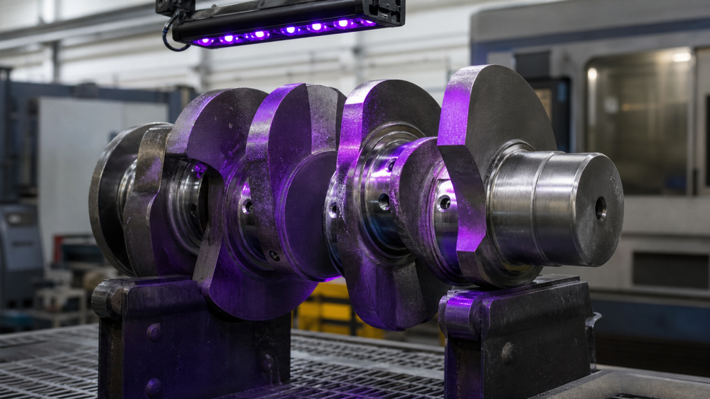
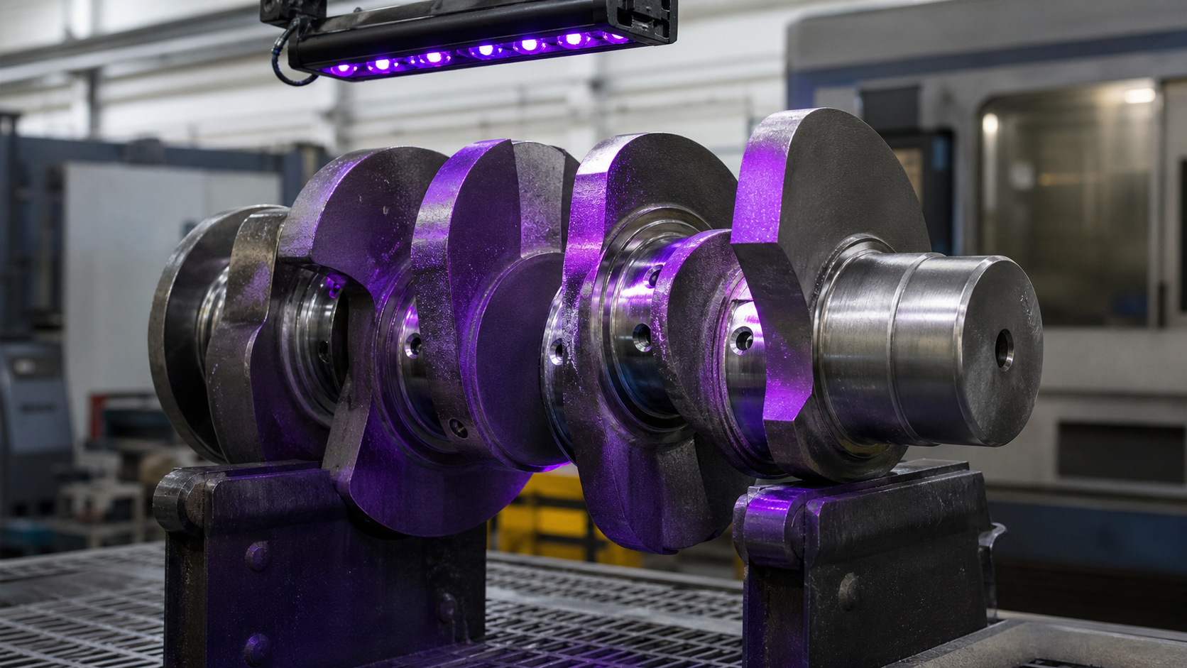
A diesel engine crankshaft converts reciprocating piston force into continuous rotary torque while enduring high cylinder pressures at peak combustion. When a cylinder fires, the combustion pulse travels through the connecting rod into the crankpin journal, bends the crank throw, twists the entire shaft, compresses the oil film at the adjacent main bearing, and sends a torsional wave through the damper and flywheel before the next cylinder fires. That load path repeats millions of times over the crankshaft’s service life, making material selection, fillet radius, heat treatment, and bearing clearance critical to durability. This article examines the loads acting on diesel crankshafts, the forging and heat-treatment practices that resist those loads, the failure modes that develop at journals and fillets, the inspection measurements that determine reusability, and the specification data required when sourcing a replacement crankshaft.
Key Takeaways
- Diesel crankshafts experience combined bending and torsion from high cylinder pressure, with peak loads concentrated at crankpin fillets during combustion events.
- Forged steel crankshafts use controlled grain flow and nitrided or induction-hardened fillets to resist fatigue initiation at stress concentrations.
- Journal failures appear as fretting, scoring, or heat discoloration; fillet failures begin as fatigue cracks that propagate until fracture.
- Runout, journal diameter, fillet radius, and surface finish must meet engine-maker limits before reuse; any crack indication requires rejection.
- Replacement crankshaft specifications must include engine model, stroke, journal dimensions, material grade, heat treatment, balancing tolerance, and any OEM part number cross-reference.
The Diesel Crankshaft Load Path
During combustion in a single cylinder, the expanding gases push the piston downward, transmitting force through the connecting rod to the crankpin journal. That force decomposes into a radial component that tries to bend the crank throw and a tangential component that applies torque to the shaft. The crankpin journal rotates within the connecting rod’s big-end bearing, supported by a hydrodynamic oil film under load.
From the crankpin, the load transfers through the crank webs—the thick sections connecting the crankpin to the main journals. The webs act as cantilever beams, bending under the reciprocating load and experiencing maximum stress at the fillet radius where the web meets the journal. That fillet is the most common initiation site for fatigue cracks because the geometry change creates a stress concentration even when the radius is properly machined.
The main journals ride in bearings mounted in the engine block, providing the primary support for the rotating assembly. Each main bearing must react not only the downward force from the connecting rod on its adjacent throw but also the cumulative torsional load from all firing cylinders. In multi-cylinder engines, the main journal nearest the flywheel sees the highest torsional stress because it carries the sum of all upstream torque pulses.
At the front of the crankshaft, a torsional damper absorbs oscillating torque waves generated by the discrete firing pulses. Diesel engines with inline six or V8 configurations produce specific harmonic orders that can excite resonance in the crankshaft if the damper is missing, incorrect, or degraded. At the rear, the flywheel adds inertia to smooth output torque and provides the mounting face for the clutch or torque converter. The flywheel flange must be perpendicular to the crankshaft centerline within the engine maker’s runout specification to prevent clutch chatter or transmission vibration.
Bending, Torsion, Cylinder Pressure, and Bearing Support
Diesel crankshafts operate under higher cylinder pressures than gasoline engines due to compression ratios typically above 14:1 and frequent use of turbocharging or supercharging. Peak cylinder pressure during combustion reaches levels that place substantial bending and torsional loads on the crankshaft assembly. The connecting rod transmits this pressure as a force that varies with crank angle, creating a pulsating bending moment on each throw.
Bending stress in the crank webs follows the classic beam equation σ = Mc/I, where M is the bending moment from the connecting rod force, c is the distance from the neutral axis to the outer fiber, and I is the section moment of inertia. The fillet radius acts as the critical section because the stress concentration factor K_t multiplies the nominal bending stress depending on the radius-to-shaft-diameter ratio. A sharp fillet raises K_t and accelerates fatigue crack initiation.
Torsional stress develops from the tangential component of the connecting rod force and accumulates along the shaft length. For a solid shaft, the torsional shear stress τ = Tr/J, where T is the applied torque, r is the radial distance from the centerline, and J is the polar moment of inertia. Multi-cylinder engines produce overlapping torque pulses that partially cancel depending on firing order and crankshaft configuration. Inline six-cylinder engines with evenly spaced throws achieve good balance, while inline four-cylinder engines exhibit a second-order rocking couple that increases main bearing loads.
Oil film thickness at the journals depends on bearing clearance, oil viscosity, shaft speed, and applied load. Under steady load, the journal rides on a wedge of pressurized oil created by the shaft’s rotation. During peak combustion pressure, the oil film thins and the journal can momentarily contact the bearing surface, leaving microscopic wear marks. Excessive bearing clearance allows the journal to move within the bearing bore, causing fretting and eventual bearing spin. Insufficient clearance starves the bearing of oil, leading to overheating and seizure.
Crankshaft deflection—the bending of the entire shaft under load—affects bearing alignment. Engine makers specify maximum allowable deflection between adjacent main journals, measured with a dial indicator while the crankshaft is installed and the engine is cold. Deflection beyond the specified limit indicates misaligned main bearing bores, a bent crankshaft, or improper main bearing cap torque.
Materials, Forging, Heat Treatment, and Fillet Strengthening
Diesel crankshafts use either cast nodular iron or forged steel depending on load requirements, production volume, and cost constraints. Cast crankshafts predominate in light-duty and automotive diesel engines where cylinder pressure remains moderate and the design can accommodate thicker sections. Forged crankshafts serve heavy-duty, high-speed diesel, and performance applications where higher strength and controlled grain flow justify the additional cost.
Nodular iron castings provide good ductility and impact resistance compared to gray iron while retaining useful damping characteristics. The spheroidal graphite structure allows the material to absorb vibration and resist sudden overload. Cast crankshafts require thicker webs to achieve equivalent fatigue strength compared to forgings because casting does not align the grain structure with the stress field.
Forged steel crankshafts commonly use medium-carbon grades such as SAE 1045, 1050, or micro-alloyed steels with vanadium or niobium additions for grain refinement. The forging process aligns the metal flow lines along the crank throw contour, placing continuous grain boundaries in tension rather than exposing weak cross-grain paths to bending loads. This fiber orientation improves fatigue life substantially compared to machined billets with random grain structure.
Heat treatment follows forging to achieve the target hardness and microstructure. Normalizing or quench-and-temper cycles produce a structure of tempered martensite or bainite with controlled hardness. Journals and fillets receive additional surface hardening to resist wear and fatigue. Induction hardening heats a shallow surface layer above the austenitizing temperature, then quenches it rapidly to form hard martensite while leaving the core tough and ductile. Nitriding diffuses nitrogen into the surface at elevated temperature for extended periods, forming hard nitride compounds without quenching distortion. Nitrided surfaces achieve very high hardness with minimal dimensional change.
Fillet rolling introduces compressive residual stress at the fillet radius after machining. A hardened roller presses into the fillet under controlled force, cold-working the surface and shifting the stress state from tensile to compressive. Fatigue cracks initiate under tensile stress, so the compressive layer at the fillet surface delays crack formation. Fillet rolling can substantially increase fatigue strength compared to an unrolled fillet with the same radius. The process requires specific tooling for each crankshaft geometry and must follow final heat treatment to avoid stress relief during subsequent heating.
Failure Evidence at Journals, Fillets, Oil Holes, and Flanges
Main and rod journal failures typically result from lubrication breakdown, bearing misalignment, or contamination. Scoring appears as longitudinal scratches in the journal surface, often with a corresponding pattern on the bearing shell. This indicates abrasive particles in the oil or momentary metal-to-metal contact during startup or overload. Fretting shows as a polished or discolored band where the journal has moved axially within the bearing, abrading both surfaces. Heat discoloration—blue, brown, or black oxide—indicates local temperatures sufficient to oxidize the steel surface, signaling oil starvation or excessive bearing clearance.
Journal ovality develops when the shaft bends under load and the bearing wears preferentially in the direction of maximum pressure. A journal that measures larger in diameter at the loaded quadrant than at 90 degrees requires either grinding to the next undersize or replacement. The engine maker’s service manual specifies maximum allowable ovality, taper, and out-of-round before machining is mandatory.
Fillet cracks initiate at stress risers such as tool marks, corrosion pits, or inclusions in the base material. A crack begins perpendicular to the maximum tensile stress, which at a fillet lies tangent to the radius and perpendicular to the shaft axis. The crack propagates in a smooth arc called a beach mark or clamshell pattern, growing incrementally with each load cycle until the remaining cross-section cannot support peak load. Final fracture is sudden and exhibits a rough, crystalline surface.
Magnetic particle or dye penetrant inspection reveals cracks before they reach critical size. Magnetic particle testing applies a magnetic field along the shaft axis and dusts the surface with iron powder. Cracks disrupt the field, causing powder to accumulate at the defect. Fluorescent penetrant testing applies a liquid dye that seeps into surface cracks, then wipes clean and applies a developer. Under UV light, the dye fluoresces at crack locations. Both methods detect small surface cracks. Any crack indication in a fillet or journal requires rejection because no reliable field repair exists for fatigue cracks in highly stressed locations.
Oil hole failures occur when cross-drilled passages interrupt the grain flow or create internal stress concentrations. Holes must be chamfered and polished to remove burrs and blend the entry radius. Cracks initiating at oil hole edges indicate insufficient chamfer or a hole location that coincides with peak bending stress. Some designs use angled drilling to position the hole away from the maximum stress region.
Flange cracks appear at the flywheel mounting face or front pulley hub, often starting at bolt holes or keyways. These cracks result from torsional vibration, imbalanced flywheels, or over-torqued bolts. A cracked flange cannot be repaired and requires crankshaft replacement. Runout measurement with a dial indicator detects flange distortion before cracks develop. Excessive runout causes clutch pulsation and can lead to bolt fatigue.
Inspection and Measurement before Reuse or Replacement
Before reinstalling a used crankshaft or machining journals for undersize bearings, verify that all critical dimensions remain within the engine maker’s reuse limits. These limits appear in the factory service manual or overhaul specification, not in generic repair guides, because they vary by engine model, bearing design, and intended duty cycle.
Runout measures shaft straightness with the crankshaft supported on the front and rear main journals in V-blocks or a lathe. A dial indicator at each intermediate main journal records total movement through one complete revolution. Runout exceeding the manufacturer’s specification indicates a bent shaft, which cannot be reliably straightened under heat because the process risks altering the heat-treated microstructure and introducing residual stress. Some marine and stationary engine makers allow limited straightening under controlled temperature using hydraulic presses and post-straightening stress relief, but this requires certified procedures and is not a field operation.
Journal diameter is measured at multiple locations—typically four points 90 degrees apart—using an outside micrometer or dial bore gauge. Record the smallest and largest readings to calculate taper and ovality. If any journal dimension falls below the minimum reuse diameter or exceeds the maximum ovality specified by the engine maker, the journal must be ground to the next standard undersize. Common undersize increments correspond to oversized bearing shells. Grinding removes material uniformly around the journal circumference and must be followed by polishing to achieve the specified surface finish.
Surface finish on journals directly affects bearing life. Engine makers specify finish in microinches Ra (arithmetic average roughness). A surface rougher than specification accelerates bearing wear by breaking through the oil film. Finish is measured with a profilometer or portable roughness tester. Journals ground outside a precision grinder often require final polishing with abrasive cloth or a belt sander equipped with fine-grit belts.
Fillet radius must be verified because grinding or improper polishing can reduce the radius and create a stress concentration. The radius is measured with radius gauges or an optical comparator. Minimum radius values appear on the engine drawing or in the service manual. A reduced radius requires blending with a fillet rolling tool or condemning the crankshaft.
Magnetic particle inspection or liquid penetrant testing follows dimensional checks. Run the test on all fillets, journals, oil hole edges, and flange faces. The procedure must meet the engine maker’s specification or an accepted industry standard such as ASTM E1444 for magnetic particle or ASTM E1417 for penetrant. Any linear indication or cluster of indications requires evaluation per the applicable standard. Conservative practice rejects any crack indication in a high-stress area.
Diesel Crankshaft Sourcing Specification
When ordering a replacement diesel crankshaft, provide the engine make, model, serial number range, and any applicable OEM part number. Engine makers sometimes change crankshaft specifications mid-production for balancing, bearing clearance, or strengthening, so the serial number determines the correct revision. If no OEM number is available, supply complete dimensional data including main and rod journal diameters, stroke, overall length, and front and rear hub configurations.
Material specification must match the original unless a documented upgrade exists. Forged steel crankshafts require the material grade—such as SAE 1045 or a proprietary alloy—and the heat treatment process including any surface hardening. Cast crankshafts require the nodular iron grade. Substituting a different material without engineering validation risks interference fits, unbalanced weight, or altered stiffness that changes the natural frequency and excites torsional resonance.
Balancing tolerance affects engine smoothness and bearing life. Production crankshafts are balanced to a residual imbalance measured in gram-inches or ounce-inches. Heavy-duty and high-speed engines require tighter tolerances than industrial or marine engines. Specify dynamic balancing if the crankshaft will be used above the engine maker’s specified speed threshold or if the engine maker requires it. Dynamic balancing corrects both static imbalance (weight offset from centerline) and couple imbalance (unequal weight distribution along the shaft length).
Machining dimensions include journal diameters, fillet radii, surface finish, and any undersize or offset grinding. If reusing connecting rods and main bearings, the replacement crankshaft must match the installed bearing size. Custom crankshafts for stroker builds or non-standard applications require a drawing with all critical dimensions, tolerances, oil passage locations, and keyway or spline details. A crankshaft manufacturer capable of custom work will review the drawing for manufacturability and may request changes to fillet radii, web thickness, or counterweight placement to avoid stress concentrations or dynamic imbalance.
Inspection and certification requirements depend on the application. Industrial and marine engines often require material test reports tracing the steel heat to the mill certificate, dimensional inspection reports verifying all critical dimensions, and non-destructive test records proving crack-free surfaces. OEM suppliers provide these documents as part of the purchase order. Aftermarket suppliers may charge separately for certified inspection or offer it as an option. For critical applications, request magnetic particle or penetrant inspection of all fillets and journals, with photographic documentation of any indications.
FAQs
Can a diesel crankshaft be welded to repair a crack?
No. Welding a cracked crankshaft introduces residual tensile stress in the heat-affected zone and disrupts the grain structure and heat treatment. The repair will fail under cyclic load. Cracks in fillets, journals, or webs require replacement. Some stationary or marine engine shops perform metal spraying or cold metal transfer repairs on non-critical areas such as keyways or flange faces, but these repairs require certified procedures and are not applicable to load-bearing regions.
How does journal diameter affect bearing oil film thickness?
Bearing oil film thickness depends on the ratio of journal surface speed to applied load, modified by oil viscosity and bearing clearance. For a given speed and load, a larger journal diameter increases surface speed and thickens the oil film. A worn or undersize journal reduces surface speed and thins the film, increasing the risk of metal-to-metal contact. This is why undersized bearings are required when grinding journals—bearing clearance must be restored to the original specification to maintain proper oil film support.
What causes a nitrided crankshaft to fail prematurely?
Nitrided crankshafts fail when the thin hardened case is breached by grinding, corrosion, or impact. Grinding a nitrided journal below the case depth exposes the softer core, eliminating fatigue resistance. Corrosion pitting from acidic oil or moisture penetrates the case and initiates cracks. Impact from dropped tools or assembly damage chips the case and creates stress risers. Nitrided crankshafts must not be ground unless the case depth specification allows it and sufficient case remains after grinding. If case depth is uncertain, treat the crankshaft as through-hardened and verify hardness after grinding.
Do all diesel crankshafts require a torsional damper?
Most diesel crankshafts require a damper to suppress torsional vibration at critical engine speeds where resonance can occur. Inline four-cylinder and V6 engines are particularly sensitive because their firing intervals produce strong harmonic excitation. Removing or installing the wrong damper shifts the resonant frequency and can cause crankshaft breakage. Some large slow-speed marine diesels and stationary engines operate below the first critical speed and may not use a damper. Consult the engine maker’s specification before removing or modifying the damper assembly.
What is the difference between static and dynamic crankshaft balancing?
Static balancing corrects weight imbalance around the crankshaft centerline by adding or removing material from counterweights until the shaft does not rotate when placed on knife edges. Dynamic balancing corrects both static imbalance and couple imbalance—the unequal distribution of mass along the shaft length that causes vibration even when static balance is achieved. Dynamic balancing requires a spinning balancer that measures vibration in two planes and calculates correction weights. High-speed and precision engines require dynamic balancing; low-speed industrial engines may accept static balancing only.
Conclusion
A diesel engine crankshaft transmits combustion force through a complex load path that combines bending, torsion, and bearing support under high cylinder pressures. Forged steel construction with controlled grain flow, induction hardening or nitriding at fillets and journals, and fillet rolling provide the fatigue strength required for millions of load cycles. Failure evidence appears as journal scoring and fretting from lubrication breakdown or as fatigue cracks initiating at fillets and propagating until fracture. Reuse decisions depend on measured runout, journal diameter, fillet radius, and crack inspection results compared to the engine maker’s limits, not generic tolerances. When sourcing a replacement crankshaft, specify the engine model, serial number, journal dimensions, material grade, heat treatment, balancing tolerance, and inspection requirements. Verify all critical dimensions with a micrometer, check fillet radii with radius gauges, and run magnetic particle or penetrant testing on all high-stress areas before installation.