
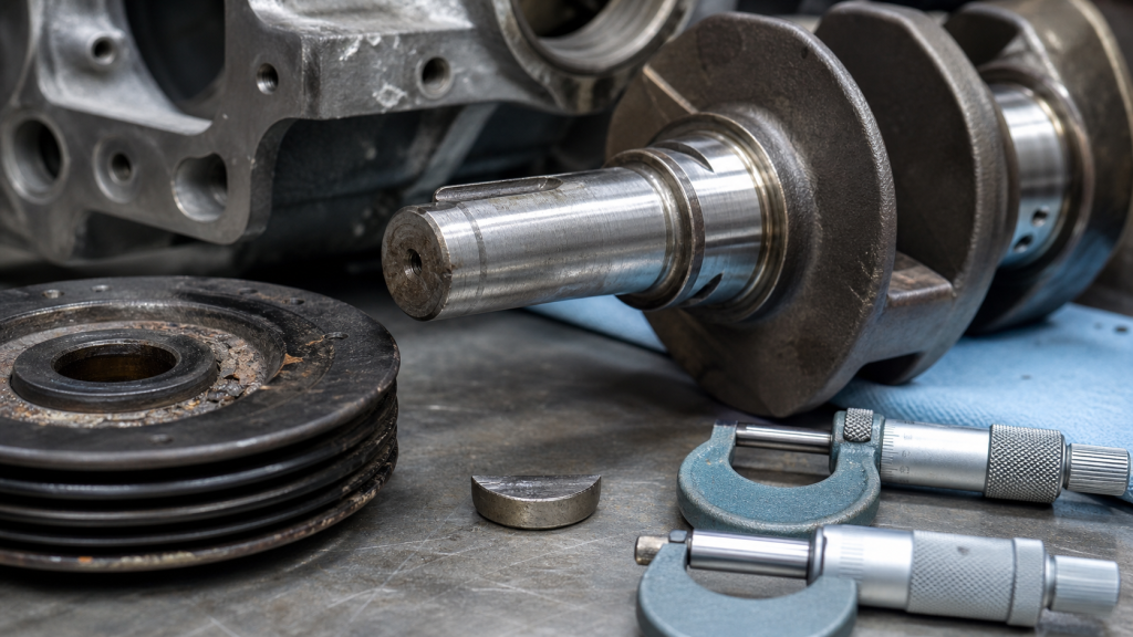
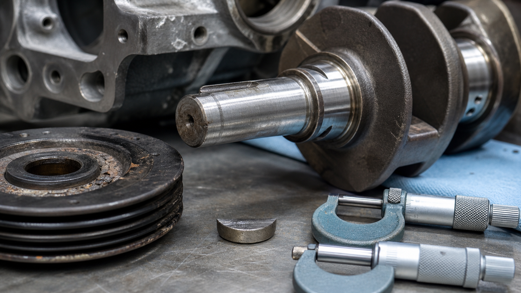
A harmonic balancer or timing gear that has rotated relative to the crankshaft nose, even though the woodruff key remains intact, points to keyway wear rather than key failure. The crankshaft keyway is a machined slot that receives a key to rotationally locate pulleys, gears, and flywheels, but it is not designed to carry torque alone. When clamp load from the retaining bolt drops or the fit loosens, the key and keyway walls experience fretting damage that enlarges the slot, allows movement, and can eventually lead to timing drift or accessory misalignment. Recognizing this damage early and measuring the shaft, key, and mating hub together determines whether a repair is feasible or whether the crankshaft requires replacement.
Key Takeaways
- The keyway provides rotational location; the bolt clamp load and friction carry most of the torque.
- Fretting wear, often called "wallering," enlarges the keyway without shearing the key.
- A pulley that has moved despite an intact key indicates looseness, not key strength failure.
- Inspect the shaft keyway, key fit, and hub bore together; a single measurement does not capture the condition.
- Welding, broaching, and sleeving repairs each introduce dimensional and material risks that must be validated against the engine maker’s limits.
- Replacement is the only safe option when the keyway damage extends into oil passages, fillets, or load-bearing journals.
What the Key and Keyway Are Expected to Do
The crankshaft keyway is a longitudinal or radial slot machined into the crankshaft nose, front hub, or flywheel flange. A woodruff key, parallel key, or half-moon key sits in this slot and engages a matching slot in the pulley, gear, or flywheel hub. The key’s purpose is to rotationally align these components during assembly and prevent them from rotating independently once the retaining bolt is torqued.
The key does not carry the full torque load in a properly assembled joint. The bolt clamp force compresses the mating faces and generates friction that resists rotation. The key acts as a locating feature and a backup stop if the clamp load is lost. In applications where the bolt cannot develop sufficient clamp—such as some early industrial engines or racing installations with minimal thread engagement—the key sees higher shear stress and the keyway walls see higher bearing pressure.
Woodruff keys are semi-circular and sit in a milled pocket, which allows some radial float but concentrates stress at the edges of the pocket. Parallel keys are rectangular and fit into a broached or milled slot that runs parallel to the shaft axis. The choice depends on the crankshaft design, manufacturing process, and whether the joint must accommodate thermal expansion or minor misalignment.
Why Clamp Load Should Carry More Than the Key
When the retaining bolt is torqued to specification, the clamped joint creates a friction interface between the crankshaft nose and the inner bore of the pulley or gear. This friction force, proportional to the bolt tension and the friction coefficient of the mating surfaces, resists the torque applied by the accessory drive or the combustion loads transmitted through the flywheel.
The key experiences minimal shear load as long as the clamp remains intact. If the bolt loosens—due to inadequate torque, thread damage, thermal cycling, or vibration—the friction drops and the key begins to carry shear load. The keyway walls then bear against the sides of the key, and the contact pressure causes localized yielding, galling, or fretting corrosion.
In diesel engines and industrial applications, the bolt is often specified with a high preload and a locking feature such as a tab washer, castellated nut, or thread locker. In automotive applications, the harmonic balancer bolt is typically a single-use stretch bolt with a controlled torque-plus-angle specification. Reusing a stretch bolt or under-torquing a standard bolt eliminates the clamp margin and shifts the load onto the key.
Fretting damage progresses faster when the joint experiences cyclic micromotion—alternating compression and tension from torsional vibration or accessory load reversals. The oxide debris generated by fretting acts as an abrasive, accelerating material loss from both the key and the keyway walls.
Fretting, Wallering, Burrs, Cracks, and Timing Movement
Fretting wear, also called "wallering" in field language, is the progressive enlargement of the keyway slot caused by repeated relative motion between the key and the shaft. The damage appears as polished or discolored surfaces, metal transfer, and a loose fit that allows the key to move axially or tilt within the slot. In severe cases, the keyway walls become rounded, the slot depth increases, and the key no longer provides positive rotational location.
A burr along the keyway edge is a secondary indicator. When the key rocks or shifts, it can peel material from the slot edge, creating a raised lip that interferes with pulley installation or removal. Burrs also concentrate stress and can initiate cracks that propagate into the fillet radius or adjacent journal.
Cracks originating from the keyway are a replacement-level defect. The keyway interrupts the shaft cross-section and creates a stress concentration, especially at the bottom corners of a broached slot or the ends of a woodruff pocket. If fretting or impact loading has work-hardened the surrounding material, the crack initiation threshold drops. Magnetic-particle or dye-penetrant inspection will reveal cracks that are not visible to the naked eye.
Timing movement is the most direct symptom of keyway wear. If the harmonic balancer, timing gear, or distributor drive gear has rotated relative to the crankshaft, the timing marks will no longer align at top dead center. Even a few degrees of rotation can shift ignition or injection timing enough to cause hard starting, detonation, or emissions failures. In distributor-equipped engines, this may also manifest as a rotor position that does not match the expected firing order.
In cases where the key has sheared completely, the failure mode is immediate and obvious: the accessory stops driving, the timing jumps, or the pulley freewheels. When the key remains intact but the keyway has worn, the failure is progressive. The pulley may slip intermittently under load, gradually walking around the shaft until the timing error becomes noticeable.
Measure the Shaft, Key, Keyway, and Mating Hub Together
Accurate diagnosis requires measuring the crankshaft keyway, the key, and the mating hub as a system. A single measurement of the keyway width or depth does not capture the total clearance or the condition of the hub slot.
Keyway width is measured with a keyway micrometer, telescoping gauge, or small-hole bore gauge. Compare the measured width to the drawing dimension or the engine maker’s wear limit. The width tolerance depends on the fit class specified by the designer; consult the repair manual or bearing supplier for acceptable clearance ranges.
Keyway depth is measured from the shaft outer diameter to the bottom of the slot, using a depth micrometer or by comparing the key height to the slot depth with a feeler gauge. If the slot has been fretted or peened deeper, the key will sit lower and may not fully engage the hub slot, reducing the effective contact area.
Key thickness and height should be checked with a micrometer. A worn or undersized key will not fill the keyway and will allow rotational slop. Some keys are manufactured with a slight taper or chamfer to ease installation, but the working faces should be flat and parallel.
Hub bore and keyway must also be inspected. Measure the hub bore diameter for ovality or taper, and check the hub keyway for width, depth, and side-wall wear. If the hub has worn more than the shaft, replacing the crankshaft will not solve the problem.
Assembled clearance is checked by installing the key and hub, then attempting to rotate the hub by hand or measuring the rotational play with a dial indicator. Any detectable movement indicates that the fit is too loose for reliable operation. Even small amounts of circumferential clearance translate to angular play that can cause timing drift.
In critical applications—such as crankshaft repair decisions for performance or industrial engines—the shaft and hub may be sent to a machine shop for coordinate measurement or optical inspection to document the wear pattern and total indicated runout.
Repair Options and the Cases That Require Replacement
Several repair strategies exist for damaged keyways, but each introduces constraints on material properties, dimensional accuracy, and fatigue life. The decision depends on the crankshaft material, the extent of wear, the operating duty, and whether the engine maker or sanctioning body permits the repair.
Welding and re-machining is the most common repair for forged-steel crankshafts. The worn keyway is filled with weld metal, stress-relieved, and re-machined to the original dimensions. This restores the slot geometry and allows the original key and hub to be reused. However, welding introduces heat-affected zones that may have lower fatigue strength than the parent material, especially if the crankshaft is induction-hardened or nitrided. The weld must be ground smooth, blended into the fillet radius, and inspected for cracks after stress relief. Some engine builders will not accept welded keyways in competition or heavy-duty applications due to the risk of fatigue failure at the repair zone.
Broaching an oversized keyway involves cutting a wider or deeper slot and installing a larger key. This is feasible if the crankshaft has enough material to support the larger slot without reducing the journal diameter or fillet strength. The hub must also be broached or milled to match, which adds cost and limits interchangeability. Oversized keys are available in standard incremental sizes from keystock suppliers, but they are not universal and compatibility must be verified against the shaft and hub dimensions.
Keyway shims or epoxy fill are temporary expedients that may stabilize a slightly worn keyway for low-load service. A brass or steel shim is inserted alongside the key to take up side clearance, or an epoxy compound is used to bond the key into the slot. These methods do not restore the original clamping geometry and will not survive high torque, thermal cycling, or vibration. They are occasionally used to return a piece of equipment to service until a replacement crankshaft can be sourced, but they should not be considered a permanent repair.
Sleeving the crankshaft nose involves machining away the damaged area and pressing or shrink-fitting a sleeve with a new keyway. This is typically done when the wear extends beyond the keyway into the pulley register or when the shaft diameter has been reduced by previous grinding. The sleeve adds mass and changes the inertia and balance of the crankshaft, so dynamic balancing is mandatory after installation. Sleeved crankshafts are common in marine and industrial rebuilds, but automotive and performance applications may reject them due to dimensional control and fatigue concerns.
Replacement is required when the keyway damage intersects an oil passage, extends into the fillet radius of an adjacent journal, or has cracked the crankshaft. Any crack originating from the keyway is a structural defect that cannot be reliably repaired by welding or filling. If the shaft has been ground undersize multiple times and lacks sufficient material for a safe weld or broach, replacement is the only option. In these cases, sourcing a new or remanufactured crankshaft from a qualified crankshaft manufacturer with the correct journal dimensions, keyway specification, and material certification is the safest path.
For engines with high production volumes, OEM replacement crankshafts are often available as service parts with the same dimensional tolerances and heat treatment as the original. For custom or obsolete engines, a billet crankshaft may be machined from a forging or solid bar, allowing the keyway to be cut to the original drawing specification or modified to accept a different accessory drive system.
FAQs
Can a crankshaft keyway be repaired without welding?
Broaching an oversized keyway or installing a sleeve are non-welding repairs, but they require machining both the shaft and the mating hub, and they change the dimensional stack. Shims and epoxy are low-strength stopgaps that will not survive sustained torque or vibration. For structural repairs, welding remains the most common method when permitted by the material and application.
How do I know if the keyway wear is from insufficient bolt torque or a defective key?
If the key remains intact and shows polished or fretted surfaces rather than shear fracture, the root cause is clamp loss, not key strength. Check the bolt for stretch, thread damage, or looseness. A defective key—undersized, soft, or incorrectly sized—will shear cleanly or deform plastically, leaving burrs or metal smear on the fracture faces.
Will a worn keyway cause engine damage beyond timing issues?
Yes. If the harmonic balancer or flywheel becomes loose, it can walk off the shaft, contact the front cover or bellhousing, or shed pieces into the oil pan. A loose balancer also reduces the damping of torsional vibration, which can accelerate fatigue in the crankshaft journals, connecting rods, and accessory drives. In the worst case, a detached pulley can rupture the timing cover or damage the front main seal, leading to oil loss and subsequent bearing failure.
Can I use a standard woodruff key in a metric crankshaft, or vice versa?
Woodruff keys are not directly interchangeable between inch and metric systems. The key width, height, and radius must match the shaft and hub keyway dimensions. Using a mismatched key may appear to fit but will leave clearance that allows movement. Always verify the key dimensions against the crankshaft and hub drawings or use a manufacturer-supplied key set.
Is it safe to reuse a crankshaft with a repaired keyway in a high-performance or racing engine?
This depends on the repair method, the material properties, the inspection results, and the sanctioning body rules. Welded keyways are generally prohibited in professional racing due to fatigue risk. Broached oversized keyways are more acceptable if the repair is documented and inspected. Always consult the engine builder, the crankshaft supplier, and the rule book before committing to a repair in a competition application.
Conclusion
A crankshaft keyway that has worn or fretted, even when the key remains intact, signals a clamping or fit problem that must be addressed through measurement, root-cause analysis, and a validated repair or replacement decision. Measure the shaft keyway, key, and mating hub together to capture the total clearance, and compare the results to the engine maker’s specification or the drawing limits. Repairs such as welding, broaching oversized, or sleeving are viable in some applications but introduce material, dimensional, and fatigue risks that must be evaluated against the operating duty and acceptance criteria. When the damage intersects structural features, oil passages, or crack-sensitive areas, replacement is the only safe choice. Document the failure mode, record the measurements, and work with a qualified machine shop or crankshaft manufacturer to ensure the repair or replacement restores the original clamping geometry and rotational accuracy.