
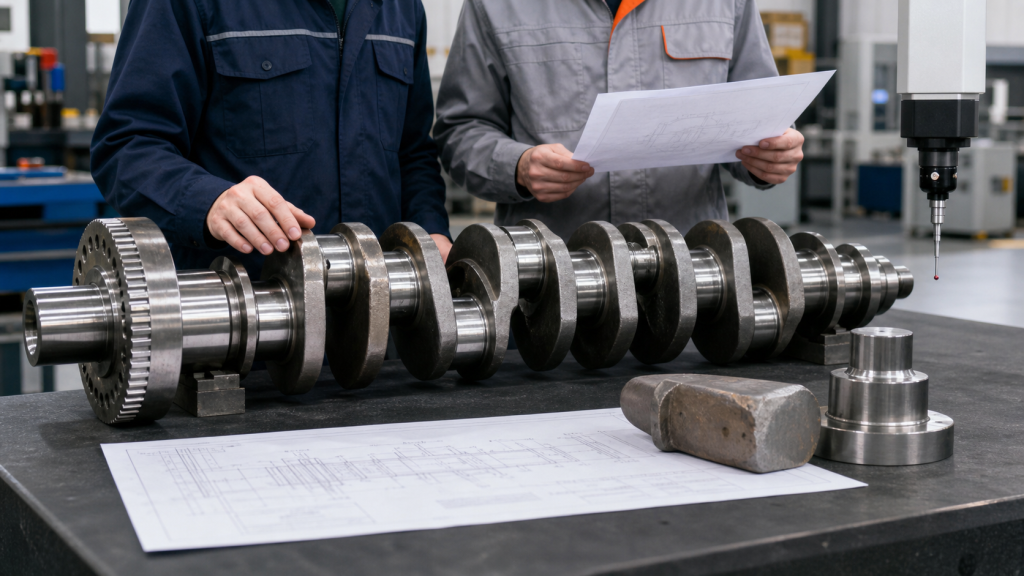
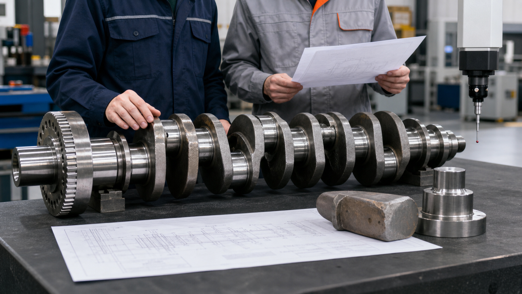
A custom crankshaft request arrives with an engine model number and a request for pricing. The model identifies a family of industrial diesel engines, but the manufacturer cannot quote without knowing which configuration, what loading, whether the original crankshaft failed, what caused the failure, and whether a verified drawing exists. A complete custom crankshaft project requires engine load data, dimensional drawings with tolerances, material specifications, heat-treatment requirements, interface dimensions for bearings and seals, oil-passage routing, and acceptance criteria that match the intended duty cycle. Without this information, the manufacturer must assume standard construction, which may not match the actual engine, leading to a part that will not fit, will not survive the operating loads, or cannot pass final inspection.
Key Takeaways
- An engine model number alone does not define journal diameters, stroke, main-bearing count, oil-hole locations, fillet radii, material grade, or heat treatment required for a replacement crankshaft.
- Manufacturing route—forged steel, cast nodular iron, or billet—depends on production volume, material cost, tooling investment, and the trade-off between grain flow and design flexibility.
- Machining tolerances for main journals, rod journals, runout, and surface finish must come from the engine maker’s drawing or an approved repair standard, not generic handbook values.
- Prototype inspection validates dimensional accuracy, material properties, surface finish, dynamic balance, and magnetic-particle or dye-penetrant crack detection before committing to production tooling.
- A quotation checklist that captures engine identity, load conditions, failure history, drawing availability, material requirements, and acceptance evidence prevents costly rework and rejected parts.
Why an Engine Model Alone Is Not a Complete Custom Crankshaft RFQ
A maintenance engineer submits a request: "Quote one replacement crankshaft for a 6-cylinder turbocharged diesel, model XYZ-480, used in a stationary generator." The model number may correspond to multiple crankshaft variants within that engine family: different main-bearing counts, different journal dimensions, different counterweight profiles, and different material specifications depending on the duty rating. Main journal diameter, rod journal diameter, stroke, oil-hole size and position, fillet radius, and counterweight profile often differ across variants of the same engine model. Without the engine serial number, the hours accumulated, the duty cycle, and either the original part number or a measured drawing from the installed crankshaft, the crankshaft manufacturer cannot determine which variant to quote.
If the original crankshaft failed, the failure mode matters. A fatigue crack starting at a fillet suggests stress concentration from an undersized radius or surface finish problem. A spun bearing indicates lubrication failure, which a new crankshaft will not fix unless the oil-pump capacity, filter condition, or bearing clearance is also corrected. Scoring on a journal surface may point to contamination, misalignment, or improper break-in procedure. Quoting a direct replacement without understanding the root cause risks repeating the failure.
The request must include measured dimensions from the failed part, the engine maker’s drawing if available, the operating hours and load profile, any visible damage or wear patterns, and the acceptance criteria the replacement must meet—whether OEM drawing tolerances, a repair manual undersize limit, or a class specification for racing or industrial equipment.
Convert Engine Loads and Interfaces into Drawing Requirements
A complete drawing specifies main journal and rod journal diameters with tolerances, crankpin offset (which defines stroke), angular spacing of crankpins for the firing order, width of each journal, fillet radii at all journal transitions, oil-hole diameter and chamfer, oil-passage internal routing, keyway or gear-mount dimensions, flywheel flange bolt pattern, front seal journal diameter and surface finish, counterweight profiles and material, and overall length. The engine maker’s drawing or approved repair standard defines the acceptable tolerance band for each dimension. Runout limits are measured at the outer main journals while the crankshaft is supported at the center mains.
If no drawing exists, reverse-engineering from the failed part requires measuring all journal diameters with a micrometer, checking runout with a dial indicator on V-blocks, verifying angular spacing with a protractor or CMM, recording fillet radii with a radius gauge, mapping oil passages by probing or sectioning a scrap part, and documenting keyway depth and width. Measurement uncertainty must be small relative to the specified tolerance.
Load data determines material selection and heat treatment. Peak cylinder pressure, mean effective pressure, maximum engine speed, and duty cycle (continuous, intermittent, or emergency rating) define the stress range the crankshaft must survive. The engine manufacturer’s specifications or a structural analysis determines the required material strength and fatigue resistance. Forged steel with high tensile strength and fatigue resistance is typical for turbocharged diesels running continuously at rated power. Cast nodular iron is acceptable for naturally aspirated or lower-speed engines with lower peak pressures. Billet crankshafts machined from heat-treated alloy bar stock suit low-volume or prototype applications where forging dies are not economical.
Bearing and seal interfaces must match the mating parts. Main bearing and rod bearing inside diameters, crush height, and oil-groove configuration depend on the journal diameter and surface finish. A ground journal finish to the engine maker’s specification is required for plain bearings; rougher surfaces accelerate wear, while excessively smooth surfaces may not retain an oil film under boundary lubrication. Front and rear seal journals require specific diameters and surface finishes, often with a lead-in chamfer to prevent seal damage during installation.
Choose Forging, Casting, or Billet Route
Forging produces a crankshaft by hot-working steel billets in closed dies, creating grain flow that follows the crankshaft contour and improves fatigue resistance. Forged steel crankshafts dominate high-performance and heavy-duty applications where alternating stress is high. Common alloys include AISI 1045, 1050, or 4340 for alloy steel forgings, with induction hardening or nitriding on journal surfaces. Forging requires custom dies, which represent a significant tooling investment that must be amortized over the production run. Setup and first-article time extends several weeks after die approval. As explained in the automobile crankshaft manufacturing process, forging delivers superior fatigue life but locks in the design—changes require new dies.
Casting uses sand molds or permanent molds to form nodular (ductile) iron crankshafts. Nodular iron contains spherical graphite nodules that improve ductility and toughness compared to gray iron. Typical grades are designated by tensile strength, yield strength, and elongation properties. Casting suits moderate-load applications and allows design changes without expensive tooling. Surface finish and dimensional precision are lower than forging, requiring more machining stock. Casting is common in automotive and light industrial engines where cost and weight matter more than ultimate fatigue strength.
Billet construction machines the crankshaft from a solid bar of heat-treated alloy steel, often 4340 or 300M. This route eliminates forging dies and provides maximum design flexibility, making it ideal for prototypes, racing engines, and low-volume custom projects. The trade-off is interrupted grain flow—machining cuts across the grain structure rather than following it—which can reduce fatigue life compared to a forged part of the same material. Billet crankshafts require more machining time and generate significant scrap. They suit applications where the production volume is low or where the design is still evolving.
Selection depends on volume, budget, and load. A single replacement for a stationary generator favors billet unless a forged blank already exists. A fleet replacement program with sufficient volume may justify forging dies. A marine engine with intermittent duty and lower peak loads may accept cast nodular iron.
Machining, Oil-Hole, Fillet, Heat-Treatment, and Balance Controls
After forging or casting, rough machining removes scale and brings journals close to final size, leaving stock for finish grinding. Finish grinding uses a cylindrical grinder with CBN or aluminum oxide wheels to achieve the final diameter and surface finish. Grinding must control dimensional tolerance, roundness, taper, and runout simultaneously according to the drawing specification.
Oil holes connect the main journals to the rod journals, supplying lubrication to the rod bearings. Hole diameter, position, chamfer, and deburring all affect oil flow and stress concentration. Undersized holes restrict flow; sharp edges create fatigue initiation sites. The manufacturer drills from the main journal through the web to the crankpin, then chamfers both ends and deburrs with brushes or abrasive flow. The intersection of the oil hole with the journal surface is a known stress riser, requiring extra attention to fillet radius and surface finish in that area.
Fillet radius between the journal and the web controls stress concentration. A larger radius lowers peak stress but requires more axial space. The drawing specifies the required radius with its tolerance. Grinding or rolling forms the fillet. Fillet rolling cold-works the surface, introducing compressive residual stress that opposes tensile fatigue stress and extends service life. Many high-performance crankshafts receive both grinding and rolling.
Heat treatment follows rough machining. Forged-steel crankshafts may be normalized, quenched and tempered, or induction-hardened at the journals. Quench-and-temper processing brings the entire crankshaft to elevated hardness, then tempers back to improve toughness. Induction hardening heats only the journal surfaces with high-frequency current, then quenches to form a hardened case that leaves a tough core. Nodular iron crankshafts are typically cast, annealed, then machined without further heat treatment, though some receive austempering for higher strength.
Dynamic balancing removes residual imbalance by drilling counterweights. The crankshaft spins on a balancing machine, which measures centrifugal force at multiple speeds. The operator calculates the correction mass and angular position, then drills material from the heavy side. Residual imbalance must stay below the specification defined for the particular engine and operating speed. Poor balance causes vibration, bearing wear, and potential fatigue damage.
Prototype Inspection and Validation before Production
First-article inspection verifies that the prototype meets drawing requirements before committing to production tooling or a batch run. Dimensional inspection measures all journal diameters, stroke, journal width, overall length, keyway dimensions, and flange bolt-hole positions using micrometers, bore gauges, height gauges, and CMM. Runout is checked with dial indicators on precision V-blocks or a crankshaft runout fixture. Surface finish is measured with a profilometer, confirming the values meet the bearing manufacturer’s or engine maker’s specifications.
Material certification verifies the heat and lot number of the forging or billet stock, confirming alloy composition and mechanical properties (tensile strength, yield strength, elongation, reduction of area, Charpy impact energy if specified). The manufacturer retains a sample coupon from each production lot for destructive testing if a failure occurs in service.
Nondestructive testing detects surface and subsurface defects. Magnetic-particle inspection (MPI) finds surface and near-surface cracks in ferromagnetic materials like steel. The operator magnetizes the crankshaft, applies ferromagnetic particles, and inspects under UV light for particle accumulations at crack sites. Liquid dye-penetrant testing suits non-magnetic materials and finds open surface cracks. The inspector applies penetrant, removes excess, applies developer, and looks for dye bleeding out of cracks. Ultrasonic testing detects internal voids or inclusions, though access and geometry can limit its application to crankshafts.
Hardness testing confirms heat-treatment results. A Rockwell or Brinell tester measures surface hardness at the journals and core hardness at a counterweight or web. Induction-hardened journals should show elevated surface hardness with a lower core hardness according to the heat-treatment specification. A hardness gradient too steep or too shallow indicates incorrect induction parameters.
Fit testing installs the prototype in the engine block with bearings, measures bearing clearance with Plastigage or a dial-bore gauge, checks end float with a feeler gauge, and confirms that the crankshaft rotates freely without binding. Any interference or excessive clearance must be corrected before production. If the original failure was a spun bearing, the inspector measures bearing crush and oil clearance to verify they meet specification.
Load testing, if required, runs the engine on a dynamometer at rated power and speed for a defined duration, then disassembles and inspects for distress. This step is uncommon for direct-replacement crankshafts but may be required for upgraded or modified designs.
Custom Crankshaft Quotation Data Checklist
A complete RFQ for a custom crankshaft includes:
Category | Required Information |
|---|---|
Engine Identity | Make, model, serial number, configuration (number of cylinders, turbo/NA), application (generator, marine, truck, industrial) |
Crankshaft Identity | OEM part number if available, or measured dimensions and photos of the existing part |
Drawings and Specifications | Dimensional drawing with tolerances, material callout, heat-treatment spec, surface-finish requirements, or engine maker’s repair manual |
Operating Conditions | Rated power, rated speed, duty cycle (continuous, intermittent, peak), hours accumulated, any overload or overspeed events |
Failure History | Description of failure (crack location, bearing condition, journal wear), photos, root-cause analysis if completed, corrective actions planned |
Interfaces and Mating Parts | Bearing part numbers or specifications, seal part numbers, flywheel and damper mounting details, gear or pulley specifications |
Quantity and Timing | Number of units required, delivery deadline, whether this is a one-time replacement or the start of a fleet conversion |
Acceptance Criteria | Dimensional tolerances, surface finish limits, hardness range, balance tolerance, inspection methods (MPI, UT, CMM), witness or third-party inspection requirements |
If a verified drawing does not exist, the manufacturer may offer reverse-engineering services, measuring the failed or reference crankshaft and producing a drawing for approval before fabrication. This adds time and engineering cost to the schedule.
FAQs
Can a Custom Crankshaft Be Made for a Motorcycle Engine?
Custom crankshaft feasibility for motorcycle engines depends on whether a forging die exists or whether billet construction is acceptable. High-performance motorcycle crankshafts often use billet alloy steel with cross-drilled oil passages and knife-edged counterweights. Production volume for motorcycle projects is typically low, making forging uneconomical unless an existing die can be adapted. The manufacturer reviews the drawing, material, machining complexity, and balance requirements before quoting. Unlike automotive or industrial applications, motorcycle crankshafts may require pressed-together construction with separate flywheels, which adds assembly and trueing operations. Confirm that the manufacturer has experience with pressed crankshaft assembly if that construction is required.
What Tolerance Should Be Used When No Drawing Exists?
When no drawing or engine maker specification exists, use the tolerance from a similar engine family or a published repair standard. For example, a heavy-duty diesel engine repair manual may specify the main journal diameter with a wear limit and a regrind undersize limit for the first undersize bearing. The replacement crankshaft should meet the original specification unless the engine is being assembled with undersize bearings, in which case the journal diameter must match the bearing size. Do not assume a universal tolerance—bearing crush, oil clearance, and load capacity all depend on the actual tolerance stack-up between the crankshaft, bearing, and housing bore.
How Is Stroke Changed in a Custom Crankshaft?
Stroke is the distance the piston travels from top dead center to bottom dead center, equal to twice the crankpin offset from the crankshaft centerline. Increasing stroke requires increasing the crankpin offset, which moves the crankpin journal farther from the main journals and increases the bending moment on the webs. The block deck height and piston compression height must accommodate the longer stroke, or the piston will strike the head or the wrist pin will hit the bottom of the cylinder. A stroker crankshaft for a racing engine requires custom pistons, longer connecting rods, and verification that the piston does not contact the head at top dead center. The manufacturer must recalculate counterweight mass and position to maintain dynamic balance with the new stroke and rod-piston assembly weight.
What Causes a Crankshaft to Fail After Replacement?
Post-replacement failure typically results from an uncorrected root cause, incorrect installation, or a defective part. Common causes include: insufficient bearing clearance, which causes overheating and seizes the bearing; excessive bearing clearance, which drops oil pressure and allows metal-to-metal contact; misalignment between main bearing bores, which loads the journals unevenly and induces bending stress; improperly torqued main bearing caps, which allow the crankshaft to shift and wear; contaminated oil, which embeds particles in the bearing surface and scores the journal; incorrect oil viscosity or pump capacity, which fails to maintain the oil film; resonance or torsional vibration, which fatigues the crankshaft if the damper or flywheel is incorrect; and improper break-in procedure, which overloads the bearings before the running-in layer is established. Inspection of the failed part and a systematic review of the installation, lubrication, and operating conditions usually identifies the cause.
Can a Crankshaft Be Repaired Instead of Replaced?
Crankshaft repair is possible when journal wear or minor damage exists but the core structure is sound. Grinding removes material from the journal diameter, creating an undersize journal that requires undersize bearings. The engine maker or repair manual specifies the maximum number of regrinds and the minimum journal diameter. Beyond that limit, the journal wall thickness is too thin, the oil-hole proximity to the surface creates a stress riser, or the bearing load capacity is insufficient. Welding can build up a worn journal, followed by machining and grinding, but the heat-affected zone may have reduced fatigue strength unless the weld procedure and post-weld heat treatment are carefully controlled. Straightening corrects minor bending from a spun bearing or installation error, but it does not restore a crankshaft with a fatigue crack or a broken journal. Magnetic-particle inspection before and after any repair confirms that cracks are not present.
Conclusion
A complete custom crankshaft project starts with a detailed RFQ that captures engine identity, load conditions, dimensional requirements, interface specifications, failure history, and acceptance criteria. Selecting the manufacturing route—forged, cast, or billet—depends on production volume, material requirements, and budget. Machining, heat treatment, and balance controls ensure that the finished crankshaft meets drawing tolerances and survives the intended duty cycle. Prototype inspection validates dimensions, material properties, surface finish, and dynamic balance before production. If you are sourcing a custom crankshaft, gather the engine serial number, measure the existing crankshaft or obtain the OEM drawing, document operating hours and any failure history, and specify acceptance criteria before requesting a quote. This information allows the manufacturer to deliver a part that fits, performs, and lasts.