
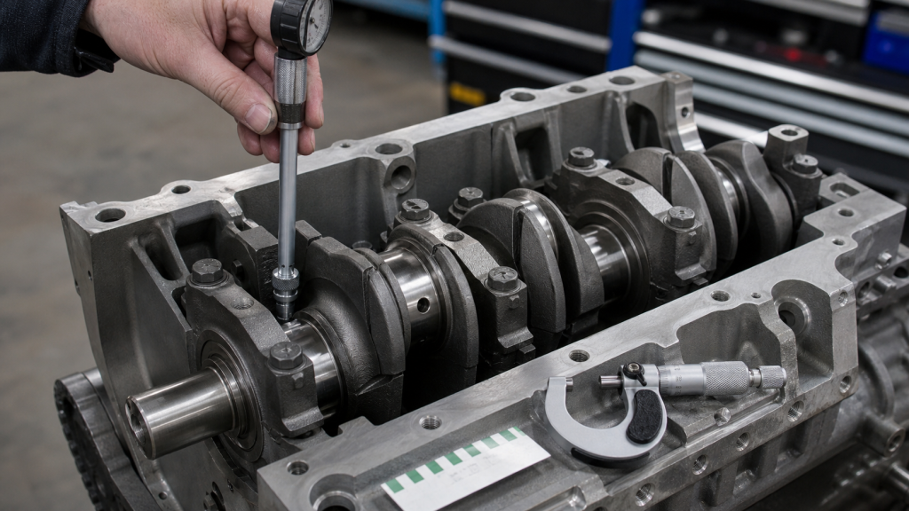
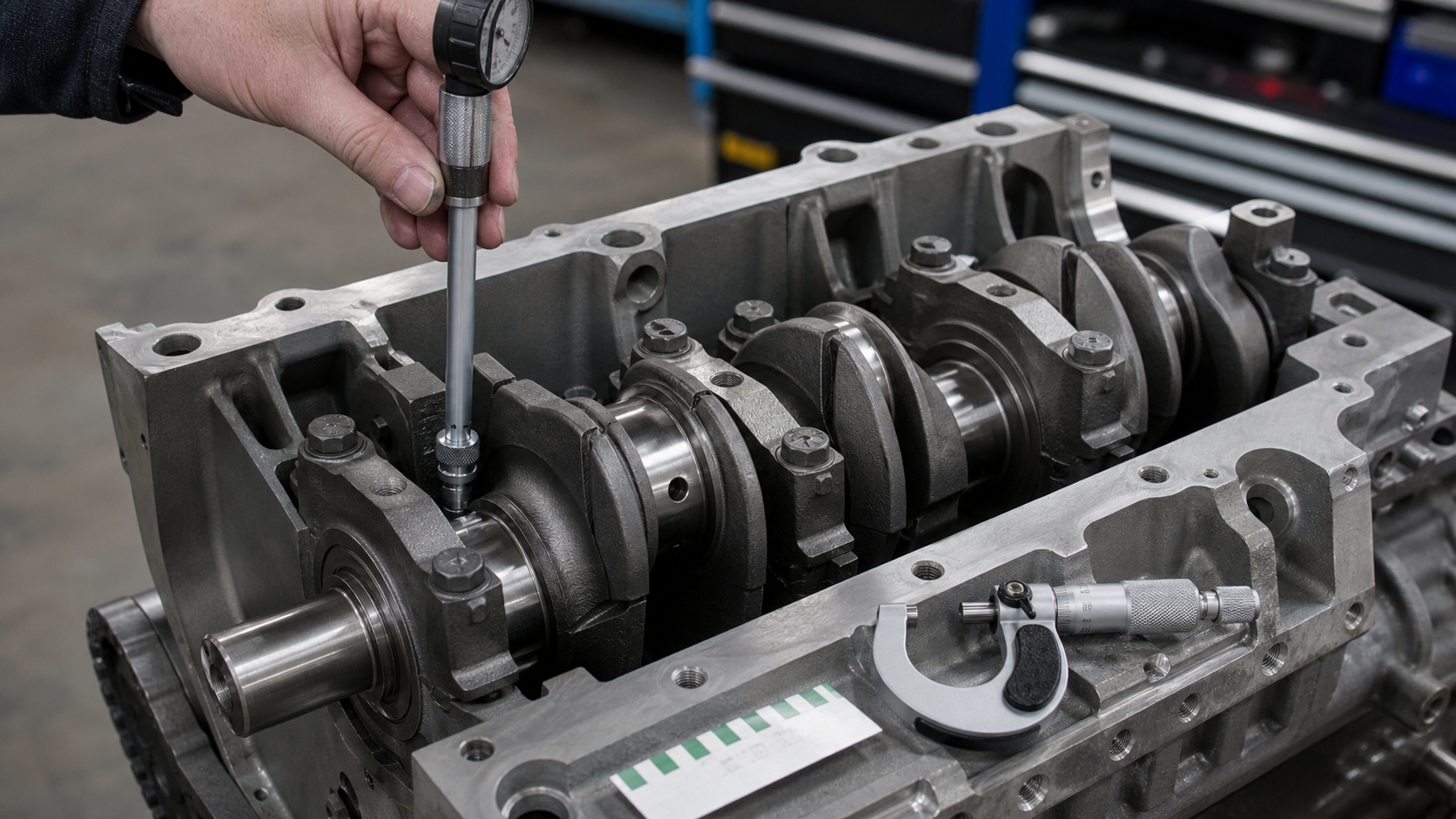
Crankshaft bearing clearance is the measured difference between the crankshaft journal diameter and the installed bearing bore diameter. This gap allows pressurized oil to form a hydrodynamic film that keeps metal surfaces separated during rotation. Too little clearance prevents adequate oil flow and causes heat buildup; too much clearance drops oil pressure and allows contact under load. Proper clearance depends on journal diameter, engine speed, oil viscosity, bearing material, and the specific limits in the engine maker’s documentation or repair manual.
Key Takeaways
- Bearing clearance is calculated by subtracting the crankshaft journal diameter from the installed bearing bore diameter, not estimated by appearance or noise.
- Hydrodynamic oil film requires both sufficient clearance space and adequate oil supply pressure to prevent metal-to-metal contact during operation.
- Micrometer and dial bore gauge give repeatable measurements for new or reground journals; Plastigage confirms assembly clearance but cannot detect taper, out-of-round, or housing bore distortion.
- Tight clearance causes heat, seizure, and bearing overlay failure; loose clearance causes pressure loss, oil starvation to other components, and fatigue-driven journal wear.
- Corrective decisions require verifying journal geometry, bearing crush, housing bore alignment, and oil system capacity against the engine maker’s specification before selecting bearings or approving a regrind.
Bearing Clearance Is a Measured Difference
Bearing clearance is not a single dimension you measure directly. Instead, you measure two separate diameters and subtract:
Clearance = Installed Bearing Bore Diameter − Crankshaft Journal Diameter
The crankshaft journal diameter is measured with an outside micrometer at multiple points around the journal and along its length. The installed bearing bore diameter is the internal diameter of the bearing shell pair after they are torqued into the connecting rod or main bearing saddle. You measure this with a dial bore gauge or inside micrometer after assembly but before installing the crankshaft.
For example, if a main journal measures 2.4985 inches and the installed bearing bore measures 2.5005 inches, the clearance is 0.0020 inches. This gap provides space for the oil film while maintaining mechanical support. The same subtraction applies to rod bearings and main bearings; only the reference specification changes.
Engine makers publish clearance limits for each journal position because larger journals need slightly more clearance to maintain the same oil-film ratio. Always use the limit from the engine’s service manual, approved drawing, or original equipment documentation rather than a generic chart. For guidance on how crankshafts are manufactured and the precision finishing processes that establish these tolerances, consult the engine maker’s specifications.
Why the Oil Film Needs Both Space and Supply
The clearance gap fills with pressurized oil delivered through drilled passages in the crankshaft and block. As the journal rotates, it drags oil into a converging wedge between the journal and bearing surface. This hydrodynamic wedge generates pressure that lifts the journal away from the bearing, forming a full oil film. The film thickness depends on journal speed, oil viscosity, bearing load, and the clearance space available.
Clearance determines oil flow rate through the bearing. Tighter clearance reduces flow but increases film pressure; looser clearance increases flow but reduces pressure. The engine’s oil pump must supply enough volume to maintain pressure across all bearings simultaneously, so total clearance across all main and rod bearings affects system performance.
Oil viscosity changes the balance. Thicker oil builds film pressure more easily but requires more clearance to flow. Thinner oil flows through tight clearances but needs higher journal speed or tighter clearance to generate sufficient film pressure. Most engine oils are multi-grade to maintain film strength across cold starts and full operating temperature.
Bearing material also matters. Tri-metal bearings with softer overlay layers tolerate brief contact better than bimetal bearings, so some performance engines run slightly tighter clearances with tri-metal bearings and synthetic oil. The crankshaft material and surface finish affect how the journal responds to borderline lubrication, but clearance and oil supply remain the primary controls.
High-speed or high-load operation demands careful clearance control. Diesel engines often specify looser clearances than gasoline engines of similar displacement because peak cylinder pressure is higher and journal speed is lower. Racing engines may use tighter clearances to maximize oil pressure at sustained high RPM, but only if oil volume and cooling are adequate.
Micrometer and Bore-Gauge Method
The micrometer and bore-gauge method measures journal diameter and bearing bore separately, then calculates clearance by subtraction. This approach reveals taper, out-of-round, and housing bore distortion that affect bearing life but would be invisible with a single-point check.
Measuring the Crankshaft Journal
Use a precision outside micrometer appropriate for the journal diameter. Clean the journal with solvent and inspect for scoring, heat discoloration, or fillet cracks before measuring. Measure at three positions along the journal length: near each fillet radius and at the center. At each position, take readings at 90-degree intervals around the circumference.
Record all readings. Compare them to identify:
- Taper: diameter change along the journal length
- Out-of-round: diameter variation around the circumference
- Wear pattern: whether the minimum diameter is at the center (normal wear) or skewed to one side (misalignment)
If taper or out-of-round exceeds the engine maker’s specification, the journal must be reground to the next undersize or replaced. Consult the service manual or approved drawing for maximum allowable taper and out-of-round for each application. Many automobile crankshaft manufacturing processes finish journals to tight geometric tolerances, so values beyond the specification indicate wear or distortion.
Measuring the Installed Bearing Bore
Install the bearing shells into the connecting rod or main bearing saddle without the crankshaft. Torque the bearing cap to specification using a calibrated torque wrench. The bearing shells must be clean and dry, with no oil or debris between the shell back and the housing.
Insert a dial bore gauge or telescoping gauge into the bearing bore. For a dial bore gauge, set the gauge to the nominal bore size using a micrometer or setting ring, then measure at the center of the bore and near each parting line. Rotate the gauge to find the minimum reading (true diameter). Record readings at 90-degree intervals to check for bore distortion.
If the bore shows out-of-round beyond the specification limit, the housing may be distorted, the bearing shells may lack proper crush, or the cap may be misaligned. Do not proceed with assembly until the cause is corrected.
Calculating and Verifying Clearance
Subtract the largest journal diameter from the smallest bearing bore diameter. This conservative calculation ensures the tightest clearance point meets the minimum specification. If the calculated clearance falls outside the engine maker’s range, determine whether the journal, bearing, or housing is out of specification before selecting a corrective action.
Document all measurements on a worksheet that lists each journal position, measurement location, and calculated clearance. This record supports warranty claims, failure analysis, and future rebuild decisions. Many machine shops use pre-printed forms that include space for before-and-after measurements, bearing part numbers, and torque values.
What Plastigage Can and Cannot Confirm
Plastigage is a crushable plastic thread that flattens between the journal and bearing when the assembly is torqued. You compare the flattened width to a printed scale to estimate clearance. The method is fast and requires no precision measuring tools, but it makes assumptions that can hide critical problems.
Plastigage Procedure
Place a short piece of Plastigage across the journal parallel to the crankshaft axis. Install the bearing cap and torque to specification without rotating the crankshaft. Remove the cap and measure the flattened Plastigage width using the scale printed on the Plastigage envelope. Wider flattening indicates tighter clearance.
Plastigage gives a single clearance value at one location. It assumes the journal is round, the bearing bore is round, and the bearing shells seat properly. It cannot detect:
- Taper: if the journal diameter changes along its length, Plastigage only measures the clearance at the thread location
- Out-of-round: if the journal or bore is oval, the measured clearance may be tighter or looser than the average gap
- Housing bore distortion: if the cap pulls the bore out-of-round during torque, Plastigage measures the distorted condition, not the final running clearance
- Bearing crush: insufficient crush allows the bearing to shift, changing clearance unpredictably
Plastigage is most reliable for verifying clearance on known-good journals and housings during final assembly. It confirms that the selected bearing size produces clearance within specification. Use it as a check, not as the primary measurement method during diagnosis or after machining.
For example, if micrometer measurements show a journal has significant out-of-round, Plastigage might give different readings in different positions, but averaging those readings would hide the geometry problem. The correct decision is to regrind the journal or replace the crankshaft, not to accept the average clearance.
Engine bearing clearance measurement using Plastigage is common in field assembly, but precision rebuilds require micrometer and bore-gauge verification to ensure journal and bore geometry meet drawing limits before clearance is calculated.
Tight-Clearance and Loose-Clearance Failure Paths
Bearing failures reveal themselves differently depending on whether clearance was too tight or too loose. Understanding the failure path helps identify the root cause and prevents repeated failures after repair.
Tight-Clearance Failures
Clearance below the minimum specification restricts oil flow and reduces film thickness. The journal runs closer to the bearing surface, generating more friction and heat. The bearing overlay softens, smears, and eventually wipes away, exposing the underlying bearing material. In severe cases, the journal and bearing seize, stopping the engine.
Visible signs of tight clearance include:
- Bearing overlay wiped or discolored in the center of the bearing span
- Blue or straw heat discoloration on the crankshaft journal
- Scored or galled journal surface where metal-to-metal contact occurred
- Bearing shells that show contact marks or pressure polishing across the full width
Tight clearance also causes a measurable drop in oil pressure during operation because restricted flow through the tight bearing reduces overall system pressure. If only one bearing is tight, oil pressure may remain normal but that bearing will fail first.
Common causes include using standard bearings on an undersize journal, incorrect bearing selection after grinding, thermal distortion of the housing during welding or machining, or dirt between the bearing shell and housing that prevents the shell from seating.
Loose-Clearance Failures
Clearance above the maximum specification increases oil flow through the bearing, reducing pressure available to other components. The thicker clearance gap allows the journal to move radially under load, causing fatigue at the journal fillet and impact loading at the bearing edges.
Visible signs of loose clearance include:
- Bearing overlay worn or eroded at the parting-line edges
- Fatigue cracks in the crankshaft fillet radius starting at the journal edges
- Oil pressure below specification at idle or low RPM
- Connecting rod bearing knock or main bearing rumble at startup or under load
Loose clearance also allows cavitation bubbles to form in the oil film as the journal moves away from the bearing under dynamic load. Collapsing bubbles erode the bearing overlay and create a pitted surface texture. This damage appears first at the loaded edge of the bearing.
Common causes include using oversize bearings on a standard journal, excessive journal wear, bearing shells worn beyond service limits, or housing bore enlarged by previous bearing spin or cap looseness.
Corrective Decisions for Journals, Bearings, Housings, and Oil
Correcting clearance problems requires diagnosing which component is out of specification and choosing a repair path that returns all dimensions to acceptable limits. The decision tree depends on measured geometry, available bearing sizes, and the engine’s remaining service life.
Decision Table: Corrective Actions by Measured Condition
Measured Condition | Journal Condition | Housing Condition | Corrective Action |
|---|---|---|---|
Clearance within spec, geometry good | In spec | In spec | Reinstall with existing bearings |
Clearance too tight | Undersize or standard | Standard bore | Install next bearing size up (more clearance) |
Clearance too tight | Standard | Bore undersized or distorted | Align bore, line bore if needed, verify bearing crush |
Clearance too loose, journal worn | Worn standard | Standard bore | Regrind journal to first undersize, install undersize bearings |
Clearance too loose, journal in spec | Standard | Bore oversized or bearing worn | Replace bearings with correct size, verify bearing crush |
Journal tapered or out-of-round | Any | Any | Regrind to next undersize or replace crankshaft |
Housing bore distorted | Any | Bore out-of-round | Align bore, check cap torque and threads, line bore if distortion exceeds limit |
Bearing Size Selection
Bearings are manufactured in standard size and multiple undersize steps. After grinding a journal to an undersize dimension, select the bearing size that produces clearance within the engine maker’s specification. Do not mix standard and undersize bearings on the same journal.
Some bearing manufacturers offer intermediate-size increments for fine clearance adjustment. These are useful when journal wear is minimal and a full standard regrind would remove too much material. Verify that the bearing manufacturer supports the specific engine model before ordering intermediate sizes.
Crankshaft Grinding Limits
Each journal can be reground a limited number of times before the fillet radius encroaches on the bearing width or the journal strength is compromised. The engine maker’s manual specifies the maximum undersize for each journal position. Consult the service documentation to determine grinding limits for the specific crankshaft design.
After grinding, the journal surface finish must meet the specification for the bearing material. Tri-metal bearings typically require finer surface finishes than bimetal bearings. Verify the grinder’s finish with a profilometer or compare against a known-good reference journal.
Housing Bore Alignment and Bearing Crush
If bearing clearance is correct but the bearing still fails, check housing bore alignment and bearing crush. Misalignment causes the bearing to load on one edge, creating a fatigue path even when clearance is within specification. Bearing crush is the interference fit between the bearing shell outer diameter and the housing bore; insufficient crush allows the bearing to spin or shift.
Measure housing bore alignment with a dial bore gauge at each main bearing saddle before and after cap torque. The bore must remain round and concentric within the specification limit. If distortion exceeds this limit, check for cracked or stretched cap bolts, damaged cap register fits, or debris in the cap joint.
Bearing crush is verified by measuring the bearing shell outer diameter and comparing it to the housing bore diameter. The shell should be slightly larger than the bore, creating interference when the cap is torqued. Insufficient crush indicates wrong bearing size, worn housing, or damaged bearing shells.
Oil System Verification
After correcting bearing clearance, verify that the oil pump capacity and system pressure meet specification at operating temperature. Total bearing clearance affects flow demand, so if multiple bearings were replaced or journals were reground, the oil pump may need to supply more or less volume than before.
Check oil pressure with a mechanical gauge at the engine’s pressure sending unit port. Pressure should meet specification at idle and at elevated RPM. Low pressure with correct bearing clearance indicates pump wear, pressure relief valve problems, or leaking oil galleries.
If the engine uses variable-displacement or variable-pressure oil pump control, verify that the control system responds correctly to clearance changes. Some modern engines adjust pump output based on bearing clearance and temperature to reduce parasitic losses.
FAQs
Can I reuse bearings after checking clearance with Plastigage?
No. Plastigage leaves a residue that contaminates the oil film and accelerates bearing wear. Bearings are also damaged by the torque cycling during Plastigage measurement. Install new bearings after any clearance check that involves removing and reinstalling the bearing caps.
How does bearing clearance change with engine temperature?
Bearing clearance increases slightly as the engine reaches operating temperature because aluminum housings expand more than steel crankshafts. The clearance increase varies by design, which is why cold-clearance specifications include a margin. Do not measure clearance on a hot engine; all specifications assume room temperature measurement.
What clearance should I use for a turbocharged or supercharged engine?
Use the engine maker’s specification for the forced-induction variant if available. If the engine was naturally aspirated and you are adding forced induction, consult the turbocharger manufacturer or engine builder for revised clearance recommendations. Higher cylinder pressure increases bearing load, which may require slightly tighter clearance to maintain film thickness, but oil cooling and flow rate must also increase to prevent overheating.
Can I mix bearing brands or types on the same crankshaft?
No. Different bearing materials have different crush, wall thickness, and clearance characteristics. Mixing brands or types produces inconsistent clearance across journals and may cause uneven loading. Use bearings from the same manufacturer and product line for all positions unless the engine maker specifies different bearing types for main and rod positions.
How do I calculate clearance if the bearing bore is oval?
Calculate clearance at the tightest point by subtracting the largest journal diameter from the smallest bearing bore diameter. If the bore is out-of-round beyond the specification limit, correct the housing bore before selecting bearings. An oval bore indicates cap misalignment, distortion, or improper bearing crush.
Conclusion
Crankshaft bearing clearance is the difference between two measured diameters, not a number estimated from noise or oil pressure. Correct clearance ensures hydrodynamic oil film formation while maintaining mechanical support and oil system pressure. Micrometer and bore-gauge measurements reveal journal taper, out-of-round, and housing bore distortion that Plastigage cannot detect. Tight clearance causes heat and seizure; loose clearance causes pressure loss and fatigue. Corrective decisions require comparing measured geometry to the engine maker’s specification, then selecting bearing size, journal regrind limits, or housing bore repair based on the specific failure path. Document journal diameters, bearing bore dimensions, and calculated clearances on a measurement worksheet, and verify oil system pressure after any bearing replacement or crankshaft regrind. For custom crankshaft manufacturing or replacement sourcing, provide the engine model, measured journal dimensions, required clearance specification, and operating duty to ensure bearing compatibility and long-term durability.