
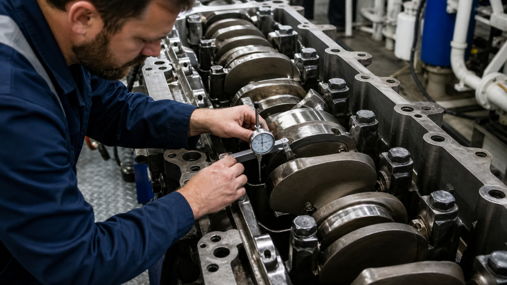
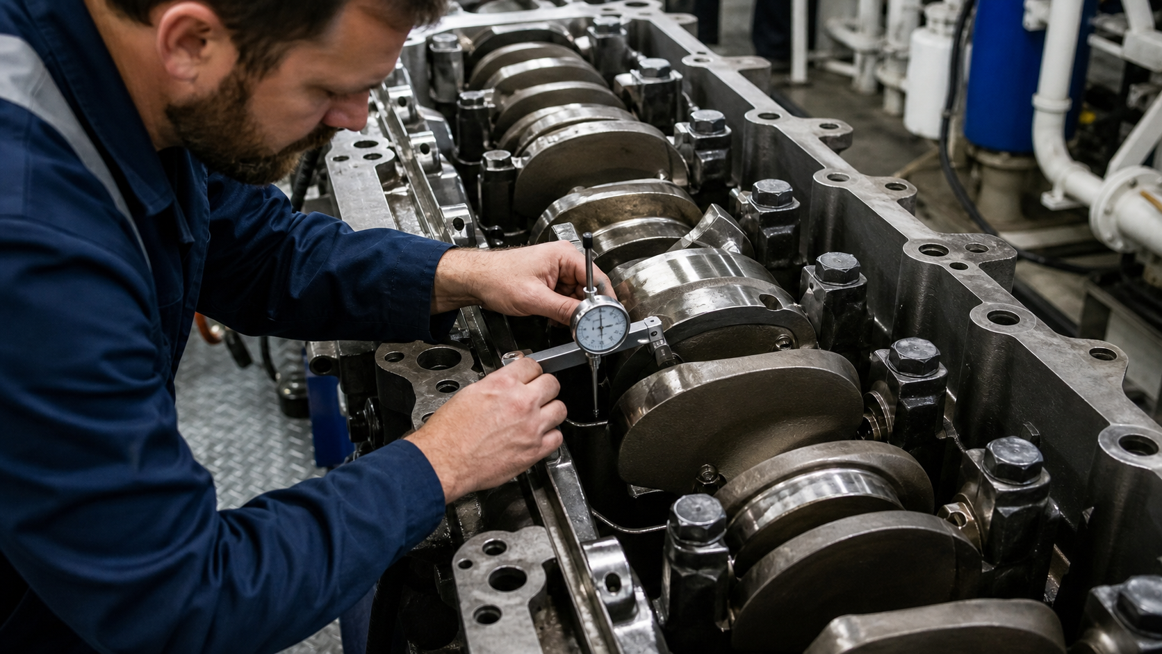
Crankshaft deflection is the measured change in distance between adjacent crank webs as the engine is turned through a full rotation. A deflection gauge placed between two webs records how the gap opens or closes at bottom dead center, port side, top dead center, and starboard side positions. The four-point pattern reveals whether main bearings are worn unevenly, whether the crankshaft has been bent by thermal stress or foundation movement, or whether the engine bedplate has sagged. Marine diesel operators measure deflection during every overhaul and after foundation work, heavy weather damage, or a bearing failure. Unlike vibration or temperature trends, deflection readings directly quantify the geometry at each main journal without disassembly.
Key Takeaways
- A deflection gauge measures the gap between crank webs at four crankshaft positions per throw, exposing misalignment, bearing wear, or hull deflection that cannot be seen with the case closed.
- Readings are recorded at bottom, port, top, and starboard positions for each cylinder, then compared against the engine maker’s cold-alignment specification and previous inspection records.
- A symmetric pattern—equal readings at top and bottom, equal readings at port and starboard—indicates straight geometry; asymmetry points to bearing collapse, foundation sag, or crankshaft bending.
- Absolute deflection limits vary by engine model, crankshaft material, stroke length, and bearing span; applying a universal tolerance will miss real problems or trigger unnecessary teardowns.
- The deflection record sheet becomes the primary evidence for bearing replacement decisions, warranty claims, and crankshaft repair or replacement specifications when patterns exceed maker limits or shift rapidly between inspections.
What a Deflection Reading Actually Represents
When a dial indicator or digital deflection gauge is mounted between two adjacent crank webs, it measures the perpendicular distance from one web face to the other. As the crankshaft rotates, firing forces, bearing reactions, and any misalignment cause the webs to move closer together or farther apart. The deflection reading is the difference between the maximum and minimum gaps observed during one full rotation, typically recorded in hundredths of a millimeter or thousandths of an inch.
The measurement reveals three failure modes that leave no other visible trace until a bearing fails or a journal cracks. First, uneven main bearing wear allows the crankshaft to sag between supports, opening the web gap at the top and closing it at the bottom. Second, thermal distortion or foundation settlement can bend the entire crankshaft, producing a consistent lean that shows up as a port-starboard imbalance. Third, a soft foot condition or fractured bedplate lets one main bearing drop, creating a localized spike in deflection at the affected throw while adjacent cylinders remain within tolerance.
The gauge does not measure crankshaft runout, which is checked with a dial indicator mounted on the main journal itself, nor does it measure journal ovality, which requires a micrometer or inside caliper after the crankshaft is removed. Deflection is a running-geometry check performed with the crankshaft installed, the main bearing caps torqued, and the engine cold.
Set the Gauge between Crank Webs Correctly
Mount the deflection gauge between the two crank webs that flank the crankpin for the cylinder being measured. Most marine diesels use a bridge-type gauge with two hardened contact points that rest against the machined faces of the webs. The gauge body spans the crankpin journal, and the dial or digital readout shows the gap. Some retrofit kits use magnetic bases clamped to one web with a spring-loaded probe touching the opposite web, but the bridge design remains standard because it self-centers and eliminates mounting-angle errors.
Before taking readings, verify that all main bearing caps are torqued to the engine maker’s specification and that the engine has been stopped long enough to reach ambient temperature. Thermal expansion from a recent shutdown will bias the readings enough to mask a developing bearing problem or falsely suggest misalignment. If the crankcase has been opened for inspection, check that no tools, rags, or fasteners are trapped between the bedplate and the hull, and confirm that the turning gear or barring motor is engaged so the crankshaft cannot shift axially during measurement.
Zero the gauge with the crankshaft positioned so the throw being measured is at bottom dead center. Some procedures call for zeroing at top dead center instead; follow the engine maker’s manual to ensure that your readings can be compared directly with previous inspections and maker limits. Record the zero position clearly on the data sheet—mixing BDC-zero and TDC-zero readings in the same trend analysis will invert the diagnostic pattern.
Record Readings through the Turning Positions
Start with the aft-most cylinder and work forward, or follow the firing order if the engine maker’s procedure specifies it. With the gauge mounted and zeroed at bottom dead center, turn the crankshaft 90 degrees using the turning gear until the throw reaches the port-side position. Record the dial reading. Continue turning another 90 degrees to top dead center, record that reading, then turn to the starboard position and record the final value. The four readings—bottom (zero), port, top, starboard—constitute one complete deflection set for that throw.
Remove the gauge, move to the next cylinder, and repeat the sequence. Most medium-speed marine diesels have six to nine cylinders; a full deflection round takes 30 to 60 minutes depending on crankcase access and gauge type. Write each reading on the data sheet as it is taken rather than relying on memory, and double-check the cylinder number and position label before moving the gauge. A transcription error that swaps port and starboard readings will produce a false misalignment diagnosis.
Some operators record deflection as the peak-to-peak span between the highest and lowest readings in the four-point set, while others plot all four values and look for pattern symmetry. Both methods work if applied consistently, but plotting all four positions gives more diagnostic information because it distinguishes vertical sag from horizontal offset. For example, a throw showing +0.15 mm at top, -0.15 mm at bottom, and zero at port and starboard indicates pure vertical misalignment, while +0.10 mm at starboard, -0.10 mm at port, and near-zero at top and bottom indicates horizontal deflection caused by hull twist or longitudinal foundation shift.
Interpret Patterns without Treating One Number as Universal
A symmetric deflection pattern—equal positive and negative excursions from zero, balanced across the four quadrants—indicates that the crankshaft is running in its designed geometry. Small absolute values confirm that the main bearings are supporting the crankshaft evenly and that the bedplate has not distorted. This baseline pattern should appear at commissioning and remain stable through the first several thousand operating hours.
Asymmetry signals a problem. If the top reading is significantly more positive than the bottom reading is negative, the crankshaft is sagging between main bearings at that throw, usually because the bearing shells have worn or collapsed. If one horizontal reading dominates—port much higher than starboard, or vice versa—the crankshaft has been pushed sideways by foundation settlement, hull deflection, or uneven bearing clearance. A sudden jump in deflection at one cylinder, with adjacent throws still normal, points to a localized failure: a cracked bedplate foot, a loose chock, or a main bearing that has spun in its housing.
Do not apply a single deflection limit across all engine types. A slow-speed two-stroke crosshead engine with long stroke and wide main bearing spacing may have deflection tolerances that accommodate the flexure designed into long crankpins, while a high-speed trunk-piston engine with short stroke and close bearing spacing may require tight limits because even small misalignment rapidly overloads the bearing edges. The crankshaft manufacturer cannot specify a deflection tolerance without the engine model, journal dimensions, bearing type, and duty cycle.
Consult the engine maker’s cold-alignment specification, found in the installation manual or the engine technical file. Most makers publish both an initial commissioning limit and a running maintenance limit; the maintenance limit is tighter because it accounts for cumulative wear and sets a threshold for corrective action before a bearing fails. If the engine technical file is not available, contact the engine maker’s service department or the classification society for guidance. Generic repair procedures describe corrective actions but cannot replace model-specific limits.
Link Deflection Trends to Bearings, Alignment, Hull, and Foundation Conditions
Deflection patterns trace back to four root causes, often working in combination. First, main bearing wear. As the white-metal or aluminum-tin bearing surface wears away, the crankshaft drops lower in the housing. Early wear is uniform and shows up as a gentle increase in top-bottom deflection across all cylinders. Advanced wear becomes localized, with the highest-loaded bearings—typically the cylinders nearest the driven equipment or the flywheel end—showing peak deflection while the lightly loaded bearings remain near baseline.
Second, crankshaft bending. Thermal shock from a cold-start overload, repeated bearing overheating, or a single severe overload event can plastically deform the crankshaft. The bent shaft will show a consistent deflection offset in one direction across multiple throws, often accompanied by a step change in the pattern where the bend is concentrated. A crankshaft that has been straightened in a hydraulic press or by local induction heating may return to tolerance, but the deflection record must be monitored closely because residual stresses can cause the bend to reappear under load.
Third, foundation and bedplate problems. Marine diesel engines are bolted to steel fabrications that flex with hull bending, vibration, and cargo loads. If the engine room structure sags or if a foundation chock cracks, the bedplate will follow, and the crankshaft will be forced into a new geometry. This produces a progressive deflection pattern—readings increase steadily from one end of the engine to the other—or a sharp discontinuity at the affected frame. Hull deflection during heavy weather or after a grounding can bend the entire engine structure without damaging the crankshaft itself; deflection readings will normalize after the hull is repaired and the engine is re-aligned.
Fourth, installation errors. If the engine was aligned with the main bearing caps loose, or if cap bolts were not torqued evenly, the deflection pattern will include random high spots that do not correlate with bearing wear or service time. A post-repair deflection check that differs drastically from the pre-repair baseline suggests that the bearing caps were disturbed during reassembly. This is why the procedure specifies measuring with caps torqued and the engine cold: it isolates geometry from transient thermal or mechanical effects.
Deflection Record Sheet and Escalation Rules
Every deflection inspection must be documented on a standard record sheet that includes the date, engine running hours, cylinder numbering convention, gauge type, zero reference position, and the four readings per throw. Attach the sheet to the engine logbook and retain it for the life of the engine. When the crankshaft is eventually removed for regrinding or replacement, the deflection history will tell the machine shop or crankshaft manufacturer where the wear or bending was concentrated and whether the damage is repairable.
Compare each new set of readings against the previous inspection and against the engine maker’s limits. If deflection has increased significantly since the last check, or if any single throw approaches the maker’s limit, escalate to the chief engineer or shore maintenance team for a bearing inspection. Do not wait for the deflection to reach the absolute limit—by that point, bearing failure is imminent and the risk of scoring the journal or cracking a crankpin fillet is high.
If the pattern shows a sudden asymmetric shift at one cylinder, stop the engine and inspect that main bearing immediately. A loose bearing cap, a spun bearing shell, or a cracked bedplate foot will worsen rapidly under load. If the pattern shows a gradual symmetric increase across all cylinders, plan a bearing inspection at the next scheduled overhaul and increase the deflection measurement frequency until the inspection is complete.
When deflection exceeds the maker’s limit and bearing inspection reveals no obvious damage, suspect a foundation or alignment problem. Measure the engine bedplate for twist using a taut wire or laser alignment system, check the foundation chocks for cracks or voids, and verify that the driven equipment—generator, gearbox, or propeller shaft—has not shifted. Marine installations are subject to hull flexure, and an engine that was perfectly aligned at commissioning may need realignment after years of heavy-weather service.
FAQs
Can deflection be measured with the engine running?
No. Firing forces, inertia loads, and thermal expansion make it impossible to position the gauge accurately or obtain repeatable readings while the engine is running. Deflection must be measured with the engine stopped, cooled to ambient temperature, and turned slowly by hand or with the barring motor.
What if deflection readings are negative at all four positions?
A consistently negative deflection set indicates that the gauge was zeroed incorrectly, or that the zero reference position was recorded backward. Re-zero the gauge and repeat the measurement. If the problem persists, check that the gauge is mounted between the correct pair of crank webs and that the dial indicator is functioning. Negative readings themselves are not mechanically significant—only the pattern and magnitude matter.
How does crankshaft deflection differ from runout?
Deflection measures the relative position of two crank webs as the crankshaft rotates in its bearings. Runout measures the radial deviation of a main journal or crankpin from true circular motion, checked with a dial indicator mounted on the journal surface itself. Runout detects a bent crankshaft or an out-of-round journal; deflection detects bearing wear, misalignment, or foundation problems. Both measurements are required during a major overhaul, but deflection can be checked without opening the crankcase.
Can a crankshaft with high deflection be repaired?
It depends on the root cause. If deflection is high because of bearing wear, replacing the bearings and re-checking alignment will usually restore normal readings. If deflection is high because the crankshaft is bent, the shaft must be removed and either straightened by a qualified machine shop or replaced. Straightening is only effective if the bend is gradual and the crankshaft has not developed fatigue cracks; crankshaft repair decisions require inspection of the journal fillets, oil passages, and thrust faces before committing to a repair process.
Do forged and cast crankshafts have different deflection limits?
Deflection limits are set by the engine maker based on bearing span, stroke length, and firing pressure, not by crankshaft material alone. A forged crankshaft and a cast crankshaft installed in the same engine model will share the same deflection tolerance because the geometry and bearing loads are identical. Material differences matter for fatigue resistance and regrind capacity, but those factors are separate from the deflection measurement. Crankshaft manufacturing processes affect dimensional stability and surface finish, which influence how quickly deflection develops in service, but they do not change the acceptable running geometry.
Conclusion
Crankshaft deflection measurement converts a hidden geometry problem into a documented, actionable data set. The four-point readings per throw reveal whether the engine is running in its designed alignment or whether bearing wear, foundation movement, or crankshaft bending has begun. Operators who measure deflection at every overhaul, compare results against maker limits and previous inspections, and escalate asymmetric or rapidly increasing patterns will catch bearing failures before they destroy the crankshaft. When deflection exceeds limits, verify the engine model and maker specification, inspect the affected bearings and foundation, and document the findings on the engine record sheet. If a crankshaft replacement or custom machining project is required, provide the deflection history, journal measurements, bearing clearances, and any evidence of bending or scoring to the machine shop or crankshaft manufacturer so the replacement part is built to correct the root cause rather than repeat the failure.