
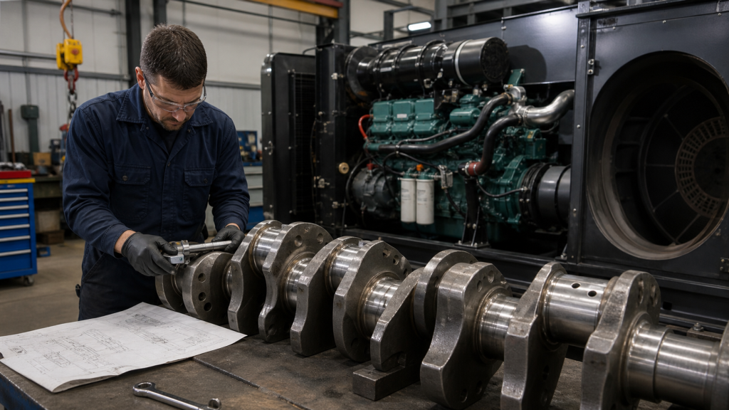
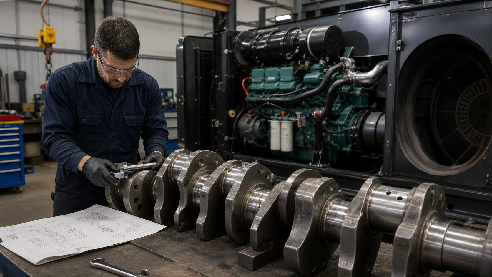
An unexpected generator outage during a peak-demand shift often points to crankshaft damage that inspection missed or duty conditions accelerated. A replacement generator crankshaft specification starts with the engine model, service manual drawing number, and observed failure mode. Standby generators experience frequent cold starts and thermal cycling. Prime-power units operate continuously at high load. Each duty profile imposes different fatigue, bearing, and balance demands on the main journals, rod journals, and counterweights. Specifying a replacement crankshaft requires the engine maker’s material grade, heat treatment procedure, journal diameter and runout limits, fillet radius, oil passage configuration, and dynamic balance tolerance. Without this data, a visually identical crankshaft may fail prematurely or cause secondary bearing and block damage. This article translates generator duty into a manufacturer-ready specification using measured inspection evidence and engine documentation.
Key Takeaways
- Generator duty cycle—standby, prime power, or continuous—directly determines crankshaft fatigue life, bearing load distribution, and acceptable inspection limits before replacement.
- Engine maker documentation provides the only valid source for main journal diameter, rod journal diameter, fillet radius, runout tolerance, and oil passage geometry for a specific crankshaft model.
- Forged steel crankshafts with induction-hardened journals suit high-load prime-power generators; cast iron crankshafts fit lower-duty standby applications where cost and weight matter more than ultimate fatigue strength.
- Measured runout, journal taper, out-of-round condition, and fillet condition from the failed crankshaft guide material selection, machining process, and acceptance criteria for the replacement.
- A complete RFQ includes engine model, crankshaft drawing or part number, material specification, heat treatment procedure, balance tolerance, inspection records, and packaging requirements to prevent repeat failure.
Generator Duty Is More Than Engine Speed and Power
Generator duty classification appears in engine maker service literature and defines expected operating hours, load profile, and maintenance intervals. Standby generators start infrequently, run at partial load during testing, and operate at full rated power only during utility outages. Prime-power generators run continuously for hours or days, supplying baseload or peaking power where grid connection is unavailable or uneconomical. Continuous-duty generators operate for extended periods at or near rated load, often in industrial cogeneration or remote-site applications.
Each duty profile imposes distinct crankshaft loads. Standby units accumulate thermal cycles from cold starts and shutdown events. The crankshaft experiences high bearing stress during cranking, then stabilizes at moderate continuous load. Prime-power units maintain steady bearing loads but accumulate high total operating hours and crankshaft revolutions. Continuous-duty units combine both: high total hours and steady high loads that test bearing clearance, journal surface finish, and oil film stability over time.
Crankshaft replacement specifications must account for these differences. A standby generator crankshaft failing after relatively few operating hours but many start cycles suggests fatigue at the fillet radius or thrust bearing surface rather than uniform journal wear. A prime-power crankshaft showing journal taper after extended operation points to inadequate bearing clearance, oil contamination, or insufficient journal hardness. The duty record, not just total hours, shapes the failure investigation and replacement material choice.
How Start Cycles, Load Steps, and Continuous Duty Affect the Crankshaft
Start cycles impose torsional shock as the starter motor accelerates the crankshaft against compression resistance. The crankshaft flexes torsionally, loading the main journals, rod journals, and fillets in bending. Repeated start cycles concentrate fatigue stress at fillet radii where the journal transitions to the crankpin or counterweight. Generators that start frequently under automatic transfer switch control accumulate fillet fatigue faster than continuously running units at the same total hours.
Load steps during generator synchronization or load transfer create transient torque spikes. The crankshaft absorbs these spikes through elastic twist and counterweight inertia. If load steps exceed the engine’s rated ramp rate, the crankshaft may experience peak stress above the design endurance limit. This condition accelerates surface cracking at journal edges and fillet roots, especially when combined with inadequate bearing clearance or oil film breakdown.
Continuous duty at rated load maintains steady bearing contact stress on the main and rod journals. Journal wear progresses gradually as bearing clearance increases and oil film thickness decreases. The crankshaft centerline deflects under combined bending and torsional loads, causing journal runout to increase over time. High-hour continuous-duty crankshafts develop measurable taper—larger diameter at the journal center than at the edges—due to uneven bearing pressure distribution. This taper appears in inspection measurements as a diameter difference that requires replacement when it exceeds the engine maker’s wear limit.
Material, Heat Treatment, Journals, and Balance Requirements
Generator crankshaft material selection depends on engine displacement, cylinder count, rated power, and expected duty. Small single-cylinder and two-cylinder portable generators typically use cast iron crankshafts. Cast iron provides adequate fatigue strength for intermittent standby duty, machines easily, and costs less than forged steel. The material’s graphite flakes interrupt crack propagation, reducing catastrophic failure risk. However, cast iron’s lower tensile strength and ductility limit its use in high-load prime-power applications.
Forged steel crankshafts suit medium and large multi-cylinder generators operating in prime-power or continuous-duty service. Manufacturers forge blanks from common alloy steel grades, then machine journals to final dimensions. Induction hardening or nitriding hardens the journal surfaces, increasing wear resistance and fatigue life without embrittling the core. The hardened case depth must exceed the maximum regrinding allowance specified in the engine service manual.
Main journal diameter, rod journal diameter, and fillet radius must match the engine maker’s drawing. A journal diameter below specification reduces bearing contact area and oil film thickness, accelerating wear. Fillet radius too small concentrates stress and initiates fatigue cracks. Fillet radius too large interferes with bearing installation or reduces bearing width. Measurement of the failed crankshaft’s journals and fillets, compared against the engine drawing, reveals whether the original part met specification or whether wear, regrinding, or manufacturing variation contributed to failure.
Oil passages drilled through the crankshaft supply pressurized lubricant from main journals to rod journals. Passage diameter, drilling angle, and chamfer details affect oil flow and entrained air. A replacement crankshaft must replicate the original passage configuration. Blocked, undersized, or misaligned oil passages starve rod bearings and cause rapid journal scoring, even when main bearing oil pressure appears normal.
Dynamic balance tolerance varies by engine speed and application. Generator engines typically operate at 1,800 or 3,600 rpm for 60 Hz output, or 1,500 or 3,000 rpm for 50 Hz output—speeds determined by the required electrical frequency and pole count. A crankshaft balanced to ISO 1940 Grade G6.3 or G2.5 keeps vibration within acceptable limits for continuous operation. The balance specification includes the target residual unbalance and the correction plane locations. The replacement crankshaft must be balanced with the same flywheel, damper, and coupling components as the installed configuration, or the generator will vibrate excessively and damage bearings or mounts.
Inspection Evidence for a Replacement Generator Crankshaft
Measured inspection data from the failed crankshaft informs the replacement specification and prevents repeat failure. The inspection sequence begins with visual examination, then progresses to dimensional measurement and surface condition assessment. Each measurement compares against the engine maker’s new-part specification and wear limits.
Main journal and rod journal diameter measurements use a precision micrometer at multiple locations along each journal length and at intervals around the circumference. Excessive out-of-round or taper indicates bearing clearance problems, misalignment, or inadequate lubrication during service. These measurements tell the inspector whether the crankshaft failed due to wear progression within design limits or whether an abnormal operating condition—oil contamination, coolant intrusion, overloading—accelerated damage.
Runout measurement places the crankshaft on V-blocks at the end journals and rotates it while a dial indicator contacts each main journal. Total indicator reading beyond the engine maker’s limit suggests the crankshaft bent under load, the block warped, or the main bearing caps shifted. A bent crankshaft cannot be straightened reliably for generator service; replacement is required. Runout data also guides manufacturing tolerances for the replacement part.
Fillet radius and surface condition at each journal-to-web transition require magnetic particle or dye-penetrant inspection. Cracks appear as bright indications under UV light after magnetic particle application. A single crack at a fillet radius justifies crankshaft replacement. Fillet cracks propagate rapidly once initiated, leading to sudden fracture. The crack location and orientation provide failure mode evidence: cracks parallel to the journal axis suggest bending fatigue from torsional loads; cracks perpendicular to the axis indicate journal distortion or bearing impact loads.
Oil passage inspection uses compressed air and light to verify hole alignment and cleanliness. A blocked oil passage causes local bearing failure and journal scoring. The replacement crankshaft’s oil passages must match the original drilling pattern and diameter. Deviations cause unpredictable bearing performance even when all other dimensions are correct.
Thrust bearing surface condition indicates whether axial loads remained within design limits during service. Scoring, galling, or discoloration on the thrust flange signals excessive end play, loss of thrust bearing clearance, or misalignment between the crankshaft and engine block thrust surfaces. This condition requires measurement of engine block thrust bearing bore condition and replacement of both crankshaft and thrust bearings to correct.
Generator Crankshaft RFQ and Acceptance Checklist
A complete request for quotation provides the manufacturer with enough information to quote the correct part without iterative clarifications. The RFQ must include:
Engine identification: Engine make, model, serial number range, and application (standby, prime, continuous). This establishes the base reference for all other specifications.
Crankshaft part number or drawing: Engine maker’s original part number, superseding part numbers, and drawing number if available. When the original part is obsolete, include measured dimensions from the failed crankshaft.
Material and heat treatment: Specify forged steel grade or cast iron grade, and required heat treatment process. If the original crankshaft’s material is unknown, inspection hardness measurements and failure mode evidence guide the material selection. Include induction hardening requirements for journal surfaces, case depth, and target surface hardness per the engine maker’s specification.
Journal dimensions and tolerances: Provide main journal diameter, rod journal diameter, journal length, and fillet radius with dimensional tolerances from the engine drawing or service manual. Include out-of-round and taper limits.
Oil passage configuration: Specify oil hole diameter, drilling angle, location, and chamfer requirements. Include a sketch or reference drawing showing passage routing from main journals to rod journals.
Balance specification: State dynamic balance grade (ISO 1940 G2.5, G6.3, or as specified), residual unbalance limit, correction plane locations, and whether the crankshaft will be balanced as a standalone component or with flywheel and damper installed.
Surface finish: Specify journal surface finish in microinches Ra or micrometers Ra per the engine maker’s requirement to maintain oil film stability.
Inspection and test requirements: List dimensional measurements, surface hardness verification, magnetic particle inspection, and dynamic balance test. State whether the manufacturer must provide inspection records with each crankshaft.
Packaging and shipping: Crankshafts require individual crating with journal surfaces protected by oil coating and plastic caps. Specify packaging requirements to prevent shipping damage.
The acceptance checklist verifies the delivered crankshaft before installation:
Inspection Item | Acceptance Criteria | Measurement Method |
|---|---|---|
Main journal diameter | Drawing nominal ±tolerance | Micrometer at multiple locations |
Rod journal diameter | Drawing nominal ±tolerance | Micrometer at multiple locations |
Journal runout | Engine maker’s limit | Dial indicator on V-blocks |
Fillet radius | Drawing nominal ±tolerance | Radius gauge |
Oil passage flow | No blockage, smooth flow | Compressed air, visual inspection |
Surface hardness | Engine maker’s specification | Rockwell hardness tester |
Dynamic balance | Specified residual unbalance limit | Balance machine report |
Surface finish | Engine maker’s specification | Profilometer or visual standard |
Installation requires clean oil passages, correct bearing clearance verification, thrust end play measurement, and runout check in the installed condition. Bearing clearance should fall within the engine maker’s specification range. Consult the service manual for thrust end play and installed runout limits specific to the engine model.
FAQs
Can a generator crankshaft be repaired by regrinding the journals?
Regrinding removes damaged journal surface material and restores smooth bearing contact, but only within the engine maker’s undersize limits. Most generator engine service manuals permit one or two regrinding steps, provided the remaining journal hardness and case depth meet minimum requirements. Regrinding beyond these limits reduces bearing contact area and fatigue strength. If the failed crankshaft already shows evidence of prior regrinding, or if journal damage exceeds the maximum regrinding allowance, replacement is required. Induction-hardened journals require specialized grinding to avoid grinding cracks in the hardened case layer.
How does a cast iron generator crankshaft differ from a forged steel crankshaft in service life?
Cast iron crankshafts suit standby and light-duty prime-power generators where start cycles and total hours remain moderate. The material’s lower cost and good machinability offset its reduced tensile strength and fatigue resistance compared to forged steel. Forged steel crankshafts provide higher fatigue strength, greater resistance to bending and torsional deflection, and longer service life under continuous high-load operation. The choice depends on engine displacement, cylinder count, rated power, and duty cycle. Replacing a cast iron crankshaft with a forged steel equivalent improves reliability in uprated or continuous-duty applications, provided the engine block and bearing design accommodate the different material properties.
What causes uneven journal wear on a generator crankshaft?
Uneven journal wear—more wear on one main journal than others, or on one side of a journal—indicates misalignment, inadequate lubrication, or bearing clearance problems. Common causes include warped engine block or crankcase, distorted main bearing caps, incorrect bearing crush, oil starvation from a plugged passage or failed oil pump, or coolant intrusion into the crankcase. Measuring each journal’s diameter at multiple locations and comparing wear patterns identifies whether the problem is localized to one journal or systemic across all bearings. The replacement crankshaft specification must address the root cause, or the new crankshaft will fail similarly. Corrective actions may include block resurfacing, bearing bore honing, or oil system modifications beyond simple crankshaft replacement.
Do generator crankshafts require certification or traceability documentation?
Generator applications in critical facilities, healthcare, data centers, or marine classification society service may require material traceability, heat treatment certification, and inspection records. The RFQ should specify required documentation, including material test reports, heat treatment furnace charts, dimensional inspection reports, and dynamic balance machine printouts. Standard commercial generator installations typically do not mandate formal certification, but documenting the replacement part’s material, dimensions, and inspection results protects against warranty disputes and provides evidence for future maintenance decisions.
How does crankshaft balance affect generator vibration and bearing life?
Inadequate crankshaft balance creates rotating unbalance forces proportional to the square of rotational speed. At generator operating speeds, even small balance errors generate significant vibration transmitted to engine mounts, generator frame, and connected equipment. Excessive vibration accelerates bearing wear, loosens fasteners, and may cause generator frame cracks or electrical connection failures over time. Dynamic balancing to ISO 1940 Grade G2.5 or G6.3 keeps vibration within acceptable limits for continuous duty. The replacement crankshaft must be balanced with the same flywheel, damper, and coupling components as the operating configuration. Balancing the crankshaft alone, then installing a different flywheel, negates the balance correction and introduces new vibration.
Conclusion
A generator crankshaft replacement specification begins with the engine model, duty cycle, and documented failure evidence, then translates measured inspection data into material, dimensional, and process requirements the manufacturer can execute. Standby duty with frequent start cycles demands different crankshaft fatigue properties than continuous prime-power operation at steady high load. Engine maker documentation provides the dimensional limits, material grades, heat treatment procedures, and acceptance criteria that prevent repeat failure. The replacement RFQ must include engine identification, crankshaft part or drawing number, material and heat treatment requirements, journal dimensions with tolerances, oil passage configuration, balance specification, surface finish, and inspection records. For additional context on crankshaft manufacturing processes, consult specialized technical resources. Measure the failed crankshaft’s journals, runout, and fillet condition to guide these requirements. Before installation, verify that the replacement crankshaft meets dimensional tolerances, surface hardness, balance limits, and oil passage flow criteria. The next step is obtaining the engine service manual, measuring the failed crankshaft, and documenting failure mode evidence to complete the manufacturer-ready specification.