
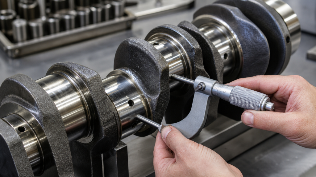
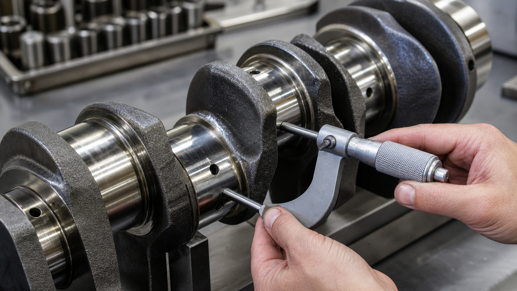
A crankshaft journal is a machined cylindrical surface on the crankshaft where it contacts a bearing—either supporting the shaft itself or transferring connecting-rod loads. Main journals rotate inside the engine block’s main bearing caps and carry the entire crankshaft assembly, while rod journals (also called crankpins) connect to the big end of each connecting rod and convert reciprocating piston motion into rotation. When you hold a micrometer against a journal surface and rotate the crankshaft 90 degrees to read the second diameter, the difference between those two readings immediately tells you whether the journal is still round or has worn oval—and whether the part can continue service, needs grinding, or must be rejected.
Key Takeaways
- Main journals support the crankshaft in the block; rod journals carry connecting-rod loads and are offset from the crankshaft centerline to create stroke.
- Taper and ovality develop when bearing clearance allows uneven contact, oil supply fails, or debris embeds in the bearing surface.
- Measure diameter at two planes per journal and at 90-degree clock positions within each plane; record all four readings to calculate taper, ovality, and out-of-round.
- Surface finish, oil-hole edges, and fillet radii affect crack initiation and bearing life; reject journals with cracks, deep scoring, or fillet damage even when diameter is within tolerance.
- Grinding removes material to restore geometry; polish removes only minor surface marks; reject the crankshaft when the ground diameter falls below the minimum repair dimension specified by the engine maker or drawing.
Main Journal vs Rod Journal: The Load Path Is Different
Main journals rotate along the crankshaft centerline and sit inside plain bearings held by the engine block and main bearing caps. These journals carry the weight of the crankshaft, absorb vertical and horizontal loads from all connecting rods, and manage thrust loads through thrust washers or flanged bearings at one or more main journal positions. Because main journals share the same axis as the crankshaft, they see relatively smooth rotational loading modulated by the sum of all cylinder firing pulses.
Rod journals—often called crankpins—are offset from the crankshaft centerline by the throw distance, which defines half the engine stroke. Each rod journal carries the connecting rod for one or more cylinders and sees a pronounced cyclic load that peaks during the power stroke and reverses during the compression stroke. The offset geometry creates a moment arm that produces torque, but it also means the bearing cap and connecting rod must clamp the journal through a load cycle that includes tension, compression, and lateral force components. Rod journal bearings typically experience higher peak unit loads and more severe oil-film conditions than main journals.
Both journal types require precise diameter, roundness, and surface finish because the bearing depends on a thin hydrodynamic oil film to separate metal surfaces. When journal geometry degrades, the oil film collapses locally, metal-to-metal contact occurs, and rapid wear or seizure follows.
Where Journal Wear, Taper, Ovality, and Scoring Come From
Journal wear starts when the oil film becomes too thin to keep the bearing and journal surfaces separated. Common causes include insufficient oil supply, contaminated oil that embeds abrasive particles in the soft bearing material, excessive bearing clearance that prevents a stable wedge-shaped oil film, or misalignment that concentrates load on one edge of the bearing.
Ovality develops when the load on a journal is not evenly distributed around its circumference. On a rod journal, the peak load during combustion pushes the journal against the bearing cap at roughly the same clock position each rotation, wearing that zone faster than the opposite side. Over thousands of hours, the journal becomes egg-shaped. Ovality is measured as the difference between the largest and smallest diameters at the same axial plane.
Taper occurs when one end of the journal wears faster than the other, creating a cone rather than a cylinder. Misalignment between the crankshaft centerline and the bearing bore is the most common cause: the journal contacts the bearing more heavily at one end, and that end wears faster. Dirt entry at one end of the bearing or uneven oil distribution can also create taper. Taper is measured as the difference in diameter between two axial planes on the same journal.
Scoring appears as parallel scratch marks running circumferentially or at a shallow helix around the journal. It results from abrasive particles—metal chips, dirt, or bearing material—trapped between the journal and bearing. Deep scoring removes the hardened surface layer on many crankshafts and exposes softer core material, which accelerates further wear.
Heat discoloration—blue, brown, or straw-colored bands—indicates that local oil-film breakdown allowed surface temperatures high enough to change the metallurgical structure. Even if the journal dimension is still acceptable, the heat-affected zone is often harder or more brittle and may crack under cyclic loading.
Journals can also develop fretting at thrust faces or fillet radii where small-amplitude motion occurs without a full oil film, and fatigue cracks that initiate at fillet radii, oil holes, or surface defects and propagate into the journal body.
How to Measure Diameter at Multiple Planes and Clock Positions
Accurate journal measurement requires an outside micrometer with resolution of at least 0.0001 inch (0.002 mm) and a clean, temperature-stable workspace. Measure each journal at two axial planes and at two clock positions within each plane, then compare the readings to detect taper, ovality, and out-of-round.
Measurement Procedure
- Clean the journal surface with a solvent and lint-free cloth to remove oil, carbon, and debris. Dirt under the micrometer anvil will add false dimension.
- Mark two measurement planes on each journal, spaced away from the bearing edges where fillet radii begin. Label them Plane A (near one end) and Plane B (near the other end).
- Establish clock positions. Rotate the crankshaft so the journal is horizontal, then measure at the 12 o’clock (top) and 3 o’clock (side) positions, or at 0 degrees and 90 degrees if you prefer angular notation. Some inspectors also measure at 6 and 9 o’clock to capture the full wear pattern, but two perpendicular readings are the minimum.
- Record four readings per journal: Plane A at 0°, Plane A at 90°, Plane B at 0°, Plane B at 90°. For a worked example with a nominal journal diameter of 2.500 inches, assume your readings are:
- Plane A, 0°: 2.4985 in
- Plane A, 90°: 2.4990 in
- Plane B, 0°: 2.4980 in
- Plane B, 90°: 2.4988 in
- Calculate taper: Subtract the smallest Plane B reading from the smallest Plane A reading. In this example, 2.4985 – 2.4980 = 0.0005 in taper.
- Calculate ovality at each plane: At Plane A, 2.4990 – 2.4985 = 0.0005 in ovality. At Plane B, 2.4988 – 2.4980 = 0.0008 in ovality.
- Determine out-of-round: The maximum reading minus the minimum reading across all four measurements gives the total geometric error. In this example, 2.4990 – 2.4980 = 0.0010 in out-of-round.
Compare these values against the engine maker’s specification. Limits for acceptable taper, ovality, and out-of-round vary by engine model, bearing type, and intended service. A crankshaft used in a stationary generator may require tighter limits than one in a truck engine due to different load cycles and expected life. Consult the repair manual or approved drawing for the specific engine you are inspecting.
Do not rely on a single diameter measurement or assume the journal is round. A journal that measures 2.499 inches at one position may be 2.497 inches at another, and that difference is enough to prevent proper bearing oil-film formation.
Surface Finish, Oil Holes, and Fillet Condition
Journal diameter alone does not determine whether a crankshaft is serviceable. Surface finish, oil-hole edges, and fillet radii control how the bearing oil film behaves and where fatigue cracks initiate.
Surface Finish
Bearing manufacturers typically specify journal surface finish requirements for hydrodynamic plain bearings. Rougher surfaces disrupt the oil film, increase friction, and wear the soft bearing material faster. Smoother surfaces improve oil retention and reduce the likelihood of metal-to-metal contact during startup or low-speed operation. Check the engine maker’s specification or bearing supplier’s data sheet for the required surface finish in microinches Ra or micrometers Ra.
After grinding, journals should be polished with fine abrasive cloth or tape to achieve the target finish. Measure surface finish with a profilometer if specifications require verification. Visible grinding marks that run circumferentially are acceptable if they fall within the Ra range, but axial or helical scratches that cross the oil-flow direction can act as leak paths and should be polished out.
Oil-Hole Edges
Crankshafts deliver oil to rod journal bearings through drilled passages that intersect the journal surface. These holes create stress concentrations and interrupt the bearing surface. Inspect each oil-hole edge for burrs, cracks, or chamfer damage. A sharp edge or burr will scrape the bearing insert and embed particles in the bearing material, which then score the journal on the next rotation.
Chamfer or radius the hole edges lightly with a stone or abrasive tool to remove burrs without enlarging the hole significantly. Do not round over the edge so much that it creates a depression; the goal is a smooth transition, not a countersink.
Fillet Radii
The fillet is the curved transition between the journal diameter and the adjacent cheek or web. This radius is the highest-stress region on the crankshaft during operation because bending loads concentrate where the geometry changes. Fatigue cracks almost always initiate at fillets, especially at rod journals where the load reverses every rotation.
Inspect fillets with a magnifying glass and bright light, looking for circumferential cracks, radial cracks, or discoloration that indicates prior overheating. Even a hairline crack is grounds for rejection because it will propagate under cyclic load and eventually fracture the crankshaft. Magnetic particle inspection or dye penetrant testing can reveal cracks not visible to the naked eye; many engine rebuild procedures require this inspection before approving a crankshaft for regrinding.
Do not grind, file, or polish the fillet radius unless the crankshaft drawing or repair manual authorizes it and specifies the allowable radius range. Reducing the fillet radius increases stress concentration and shortens fatigue life. Increasing the radius may undercut the adjacent bearing surface.
Polish, Grind, Repair, or Reject: A Measurement-Based Decision
Once you have measured diameter, taper, ovality, surface finish, and inspected for cracks and scoring, compare your findings against the engine maker’s specification or the crankshaft drawing to decide whether to polish, grind, or reject.
Polish
When: Diameter is within tolerance, taper and ovality are below the maximum allowed, surface finish is acceptable, and the only defects are minor scuff marks or light discoloration with no cracks.
Method: Wrap fine abrasive cloth (commonly 400- to 600-grit) around the journal and rotate the crankshaft in a lathe or by hand to remove surface marks. Follow with crocus cloth or finer abrasive to achieve the target Ra. Polishing removes minimal material—typically a few ten-thousandths of an inch—not enough to change bearing clearance significantly, but enough to improve oil retention and remove incipient scoring.
Result: The journal returns to service at its original diameter with standard bearings.
Grind
When: Diameter is undersized, or taper and ovality exceed the maximum allowed, but the journal has no cracks and the measured diameter is still above the minimum repair dimension listed in the engine manual.
Method: Mount the crankshaft in a precision grinder with centers in the front and rear main journals (or in the case of an offset grind, with the rod journal indexed to the correct throw). Grind the journal to the next standard undersize—commonly 0.010, 0.020, or 0.030 inch under the nominal diameter, depending on the engine and the availability of undersize bearings. Grinding must restore the journal to round and parallel within the tolerance specified by the engine maker. After grinding, polish to the required surface finish.
Result: The crankshaft is returned to service with undersize bearings that match the new journal diameter. The engine maker or bearing supplier must confirm that undersize bearings are available for your crankshaft model.
Engine manuals specify the smallest allowable journal diameter, often called the minimum regrind dimension or discard diameter. For example, a main journal with a nominal diameter of 2.500 inches might have a minimum dimension of 2.470 inches. If grinding to remove taper or scoring would take the journal below 2.470 inches, the crankshaft must be rejected. Do not exceed this limit. Grinding past the minimum dimension leaves insufficient material to carry the load, and the thinner journal may deflect under load or crack at the fillet.
Weld Repair and Metal Spray
Some crankshafts can be repaired by welding or thermal spraying the journal surface, then regrinding to the original diameter. This approach is common for large diesel crankshafts where replacement cost is high and the material and welding procedure are proven. However, weld repair is not universally applicable. The crankshaft material must be weldable without preheating or post-weld heat treatment that could distort the entire shaft, and the repair procedure must be qualified to prevent hydrogen cracking or lack of fusion. Do not attempt weld repair unless the engine maker, classification society, or applicable standard approves the procedure and you have verified welder qualification, preheat, filler material, and post-weld inspection requirements.
Reject
When: The journal has cracks at the fillet or oil hole, scoring that penetrates the hardened case (if present), or diameter below the minimum repair dimension.
Why: Cracks propagate under cyclic load and will cause sudden fracture. Removing enough material to grind out a crack usually takes the journal below the minimum dimension. Scoring that reaches the core material accelerates wear and cannot be polished out without removing excessive material. Heat discoloration that indicates metallurgical change may have embrittled the surface and created subsurface cracks not visible on the surface.
Rejection is a final decision. Do not attempt to save a cracked crankshaft by grinding away the crack unless the engine maker provides a specific repair procedure with dimensional and inspection limits. For guidance on how to repair a crankshaft when repair is permissible, or to understand how crankshafts are manufactured to prevent these failure modes, consult specialized resources.
FAQs
Can I measure a crankshaft journal with a caliper instead of a micrometer?
A caliper may be adequate for rough screening, but it lacks the resolution to detect small taper or ovality. Use an outside micrometer with 0.0001-inch resolution for journal inspection and bearing clearance verification.
What causes one rod journal to wear faster than others?
Uneven wear across rod journals usually indicates a cylinder-specific problem: a failed injector or spark plug that changes combustion pressure, a bent connecting rod, a failing bearing that allows excessive clearance, or uneven oil delivery due to a blocked passage. Measure each journal individually and inspect the corresponding connecting rod and bearing for damage.
Do forged and cast crankshafts have different journal wear limits?
The material does not change the geometric tolerance for taper, ovality, or surface finish, but it does affect regrind limits. Forged crankshafts typically have a through-hardened or induction-hardened journal that retains hardness after grinding, so they can often be ground to smaller diameters. Cast crankshafts may have a shallow hardened case; grinding through the case exposes softer material that wears faster. Check the crankshaft drawing or engine manual for the minimum regrind dimension specific to your crankshaft material and heat treatment.
How do I know if undersize bearings are available for my crankshaft?
Consult the engine parts catalog or contact the bearing manufacturer with your engine model and crankshaft part number. Common passenger-car and light-truck engines have undersize bearings in 0.010, 0.020, and sometimes 0.030-inch increments. Heavy-duty diesel and industrial engines may offer additional undersize steps or metric undersize bearings. If standard undersize bearings are not available, grinding the journal to an arbitrary dimension will leave you with no matching bearing and an unusable crankshaft.
What is the difference between runout and ovality?
Runout is the total indicator reading (TIR) when you mount a dial indicator against a journal and rotate the crankshaft through 360 degrees in V-blocks or lathe centers. It measures how much the journal centerline deviates from the main journal centerline—a combination of journal ovality, offset error, and crankshaft straightness. Ovality is the difference between the largest and smallest diameters at a single axial plane on one journal. A journal can be perfectly round (zero ovality) but still show runout if the crankshaft is bent or the journal is machined off-center.
Conclusion
Journal condition determines whether a crankshaft can return to service with standard bearings, requires grinding to an undersize dimension, or must be rejected. Measure each main journal and rod journal at two planes and two clock positions, compare the readings to detect taper and ovality, and inspect fillets and oil holes for cracks and burrs. Do not rely on visual inspection or a single diameter reading. The decision to polish, grind, or reject must follow the engine maker’s specification or the crankshaft drawing; universal limits do not exist because bearing clearance, material, and load conditions vary by engine model and application. If the measured journal diameter falls below the minimum repair dimension or if cracks appear at fillets or oil holes, reject the crankshaft. For replacement crankshafts or technical support on custom forgings, contact a crankshaft manufacturer with your engine model, measured dimensions, and failure evidence to ensure the replacement meets your material, geometry, and process requirements.