
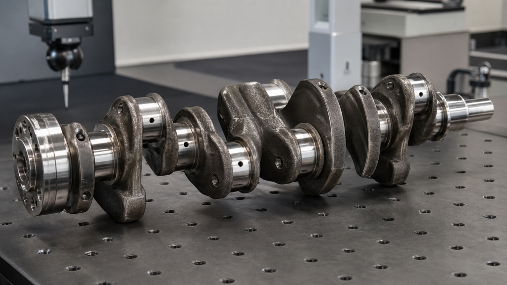
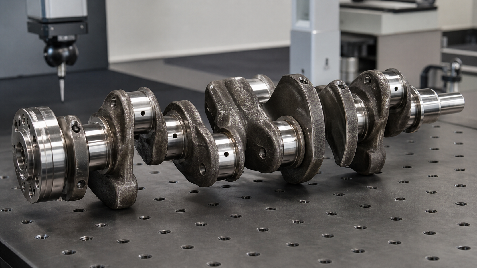
A crankshaft converts reciprocating piston motion into rotary power, and every machined feature on its surface manages a specific engineering constraint. Main journals ride in stationary bearings that carry radial load from all cylinders. Rod journals connect to reciprocating piston assemblies and transmit combustion force into rotation. Counterweights offset the inertia of those throws to reduce vibration. The flange mounts the flywheel or flexplate, while the nose drives accessories. Oil holes feed pressurized lubricant to each bearing surface, and fillets reduce stress concentration where journal diameters change. Thrust faces resist axial movement from clutch engagement or torque converter thrust. Each part is dimensioned, positioned, and finished to meet the engine maker’s specification, and inspection or replacement decisions depend on measured geometry, visible damage, and operating history rather than appearance alone.
Key Takeaways
- Main journals support the crankshaft in the block and carry radial load from all cylinders; rod journals connect to piston assemblies and convert linear force into rotation.
- Counterweights offset reciprocating and rotating mass to keep first-order and second-order inertia forces within balance limits for the engine configuration.
- The flange transmits torque to the flywheel or flexplate, the nose drives accessories or vibration dampers, and keyways or gears time valves and pumps.
- Oil holes deliver pressurized lubricant to each bearing surface; fillets reduce stress concentration at diameter changes; thrust faces control axial position under clutch or converter load.
- Inspection requires measured runout, journal diameter, fillet radius, oil-hole cleanliness, and surface finish compared to engine-maker or machine-shop limits, not visual judgment.
- Replacement or repair decisions depend on the crankshaft drawing, material and construction method, operating duty, measured wear or damage, and approved machining or balancing procedures.
A Functional Map of the Crankshaft
Crankshaft geometry is dictated by the number of cylinders, firing order, and engine architecture. A crankshaft manufacturer machines or forges each feature to carry a specific load, enable an assembly interface, or route pressurized oil. The main journals are concentric with the crankshaft centerline and ride in bearings installed in the engine block. The rod journals are offset from the centerline by the crank radius and connect to the small end of each connecting rod. The distance between the main-journal and rod-journal centerlines defines the crank throw, which controls piston stroke. Piston stroke equals twice the crank radius.
Webs connect adjacent journals and provide the structural path for bending and torsional loads. Counterweights are integral masses or bolted-on pieces that offset the inertia forces generated by the reciprocating piston assemblies and rotating rod journals. The flange face at the rear of the crankshaft bolts to the flywheel or flexplate. The nose at the front carries the vibration damper, accessory drive pulley, or timing gear. Keyways, splines, or threaded holes lock these components against rotation.
Oil passages drilled through the main journals and connecting webs deliver lubricant to each rod journal. Fillets blend the diameter transition between journals and webs to reduce stress concentration. Thrust faces on one main journal or a dedicated thrust bearing absorb axial loads from clutch engagement, torque converter thrust, or propeller thrust in marine applications. Each feature is dimensioned and toleranced on the engine maker’s drawing, and deviations outside those limits affect bearing clearance, oil pressure, balance quality, or structural integrity.
Main Journals and Rod Journals Support Different Interfaces
Main journals are the stationary bearing surfaces that support the crankshaft in the engine block. They are concentric with the crankshaft axis and sized to provide adequate load-carrying area for the hydrodynamic oil film. Main-journal diameter varies with engine size and application; the engine maker’s drawing specifies the nominal dimension and acceptable tolerance. The number of main journals equals the number of cylinders plus one in most inline configurations, which places a main bearing between each pair of rod journals and at each end of the crankshaft. This arrangement minimizes bending deflection under firing loads.
Rod journals are offset from the main-journal centerline and rotate around it, creating the eccentric motion that converts piston reciprocation into crankshaft rotation. The rod journal diameter is typically smaller than the main journal diameter to reduce the rotating mass moment of inertia and to allow adequate web width for load transfer. Each rod journal supports one connecting rod in a single-cylinder or inline engine, or two connecting rods in a V-configuration where paired cylinders share a common crank throw.
Journal surfaces are ground to a finish and diameter tolerance specified by the engine maker to maintain proper bearing clearance. Bearing clearance is the diametral difference between the journal and the installed bearing. Excessive clearance reduces oil-film stiffness and increases vibration; insufficient clearance risks bearing seizure under thermal expansion. Journals that are worn beyond the minimum diameter specified on the engine drawing must be undersize-ground in steps defined by the bearing supplier, and matched with undersize bearings.
Main journals carry radial load from all cylinders and must resist bending moments created by firing forces and inertia loads. Rod journals carry the direct combustion load from a single cylinder or pair of cylinders, plus the inertia load from the reciprocating assembly. The transition between main and rod journals creates a bending-stress concentration, which is why fillets are machined at these locations and why cracks often initiate there when fatigue limits are exceeded.
Webs, Throws, and Counterweights Manage Geometry and Inertia
Webs are the structural arms that connect adjacent journals. They transmit bending and torsional loads from each rod journal to the nearest main journals, and they provide the mass and stiffness required to maintain journal alignment under operating loads. Web thickness and radius are sized to keep deflection and stress below fatigue limits while minimizing rotating inertia. In a billet crankshaft, webs are machined from solid bar stock. In a forged crankshaft, webs are formed in the die and then finish-machined to final dimensions.
The crank throw is the radial distance from the main-journal centerline to the rod-journal centerline, and it equals half the piston stroke. Throw geometry determines the inertia forces generated during each revolution. A longer throw increases displacement and torque but also increases piston speed and secondary inertia forces. Multi-cylinder engines index the throws according to firing order to distribute power pulses and cancel certain inertia harmonics.
Counterweights offset the centrifugal force created by the rotating rod journals and a portion of the reciprocating mass. They are typically cast or forged integral with the webs, though some racing and heavy-duty crankshafts use bolt-on counterweights that can be adjusted or replaced. Counterweight mass and placement are calculated to minimize first-order and second-order inertia forces at the crankshaft’s main bearings. Perfect balance is achievable only for certain engine configurations, such as inline six-cylinders and flat-plane V8s. Other layouts such as inline four-cylinders and 90-degree V8s with cross-plane cranks require external balance mass on the flywheel, damper, or both.
Balance quality is expressed as the residual unbalance per unit mass. Automobile crankshaft manufacturing processes include dynamic balancing on two-plane machines that measure and correct unbalance in two correction planes near the ends of the crankshaft. Rebuilders must rebalance the crankshaft after grinding journals undersize, replacing counterweights, or welding repairs, because material removal or addition changes the mass distribution.
Flange, Nose, Keyway, and Gear Connect the Rest of the Engine
The flange is the mounting face at the rear of the crankshaft where the flywheel or flexplate bolts on. It is machined perpendicular to the crankshaft axis and may incorporate a pilot bearing bore, bolt-hole pattern, and register diameter for flywheel centering. Runout at the flange face and pilot bore must remain within the engine maker’s limits to prevent flywheel wobble, clutch chatter, or transmission input-shaft misalignment.
The nose is the front end of the crankshaft that extends beyond the front main journal. It carries the vibration damper, accessory drive pulley, and often a timing gear or sprocket. A keyway or Woodruff key slot locks these components against rotation. The nose diameter and key dimensions are specified on the crankshaft drawing, and wear or damage in the keyway can allow the damper or pulley to slip, leading to timing errors or accessory-drive failure.
Some diesel engines machine a gear directly onto the crankshaft nose to drive the camshaft, injection pump, or oil pump. Gear teeth are hardened by induction or carburizing to resist wear, and tooth-flank damage or timing errors require crankshaft replacement or gear repair according to the engine maker’s procedure. Marine and industrial engines may extend the nose through a seal housing to drive a power take-off or front-mounted pump.
Threads at the nose end secure the damper retaining bolt, and thread damage from improper installation or removal requires thread repair or crankshaft replacement. The nose is also a common location for a timing mark, either machined into the surface or cast into a flange, that aligns with a pointer on the engine front cover to indicate piston position during timing and adjustment procedures.
Oil Holes, Fillets, and Thrust Faces Protect Service Life
Oil holes deliver pressurized lubricant from the engine’s main oil gallery to each main journal, then through drilled passages in the webs to each rod journal. Oil enters the main journal through a hole drilled radially from the journal surface into a cross-drilled passage, then travels through the web to exit at the rod journal. Some crankshafts use angled or tangential drilling to reduce oil velocity and pressure loss. Oil-hole edges are chamfered or radiused to minimize stress concentration and prevent crack initiation.
Plugs seal the ends of cross-drilled passages to maintain oil pressure. These plugs are press-fit, threaded, or welded depending on the crankshaft design and manufacturing process. A loose or missing plug causes immediate oil-pressure loss and bearing failure. Rebuilders must clean all oil passages with brushes and compressed air to remove sludge, metal particles, and abrasive debris left by machining operations. Contaminated oil passages are a common cause of repeat bearing failure after rebuild.
Fillets are the radiused blends machined between journals and webs where the diameter changes. They reduce stress concentration by distributing bending and torsional loads over a larger area. Fillet radius is specified on the crankshaft drawing and varies with engine size and application. Grinding or polishing the fillets during journal regrinding is essential to prevent fatigue cracks, which typically initiate at the journal-to-web fillet due to the combined effects of stress concentration, surface finish, and cyclic bending load.
Thrust faces are the flat surfaces on the sides of one main journal or a separate thrust-bearing flange that absorb axial loads. Clutch engagement, torque-converter thrust, or propeller thrust in marine engines create axial force that would otherwise move the crankshaft fore or aft in the block. The thrust bearing resists this force and maintains axial position within the end-play limit specified by the engine maker. Excessive thrust-face wear increases end play and allows the crankshaft to shift during clutch operation, causing gear-rattle, clutch-release problems, or transmission misalignment.
Inspection Checklist by Crankshaft Feature
Measured inspection is required before any crankshaft repair decision to determine whether grinding, welding, or replacement is appropriate. Each feature must be compared to the limits in the engine maker’s service manual, machine-shop manual, or original drawing.
Main journal and rod journal diameter: Measure with a micrometer at multiple locations around the circumference and along the journal length. Compare to the nominal diameter and minimum regrind diameter. Taper and out-of-round beyond the engine maker’s limit require grinding to the next undersize.
Journal surface finish: Inspect visually for scoring, galling, heat discoloration, or embedment of bearing material. Measure surface roughness with a profilometer if limits are specified. Journals with deep scratches, hard spots, or case damage may not clean up at standard undersize steps.
Runout: Mount the crankshaft in V-blocks or between centers and rotate while measuring total indicator reading at each main journal and rod journal. Excessive runout requires straightening or replacement, depending on the engine application and crankshaft construction. Compare measured runout to the engine maker’s specification.
Fillet radius and condition: Inspect fillets with a radius gauge and magnification. Look for cracks, nicks, grinding burns, or inadequate blending. Magnetic-particle or dye-penetrant inspection detects surface cracks that are invisible to the naked eye. Cracks in fillets are cause for replacement in most applications, though some heavy-duty crankshafts allow weld repair under approved procedures.
Oil-hole cleanliness and plug condition: Flush all oil passages and verify flow with compressed air. Inspect plugs for security and sealing. Remove rust, sludge, and debris that could dislodge during operation and damage bearings or oil-pump pickup screens.
Flange and nose runout: Indicate the flange face and pilot bore while rotating the crankshaft. Measure nose runout at the damper mounting surface. Runout beyond limits causes vibration and component wear even if journal dimensions are acceptable.
Thrust-face wear: Measure thrust-face thickness or depth and compare to specifications. Measure crankshaft end play in the assembled engine. Excessive wear requires thrust-bearing replacement, thrust-face regrinding, or crankshaft replacement depending on available repair procedures.
Keyway and thread condition: Inspect keyways for wear, deformation, or cracks. Check nose threads for damage or stretch. Thread inserts or oversize keys may be acceptable under some service manuals but are often prohibited in high-performance or certified applications.
Record all measurements and compare them to the acceptance criteria before deciding on grinding, repair, or replacement. A crankshaft that meets dimensional limits but shows heat checking, case damage, or fatigue cracks is not reusable.
FAQs
Can a crankshaft with a crack in the fillet be repaired by welding?
Some heavy-duty diesel and industrial engines permit weld repair of fillet cracks under approved procedures that specify preheat, weld filler, post-weld stress relief, and re-inspection by magnetic-particle or ultrasonic testing. Automotive and high-speed applications typically prohibit weld repair because the heat-affected zone and residual stress create a high risk of repeat cracking. Consult the engine maker’s service manual and the applicable machine-shop or overhaul manual before attempting weld repair on any crankshaft.
How do I determine the correct undersize for journal regrinding?
Measure the journal diameter and subtract the measured diameter from the nominal diameter to find the total wear or out-of-round. Round up to the next standard undersize step available from the bearing supplier. Common undersize steps include 0.010 inch, 0.020 inch, 0.030 inch or metric equivalents such as 0.25 mm, 0.50 mm, 0.75 mm, and 1.00 mm, though actual availability depends on the manufacturer. The final ground diameter must remove all wear, scoring, and taper while leaving enough material to maintain structural strength. The engine maker’s service manual specifies the minimum allowable journal diameter; grinding beyond that limit requires crankshaft replacement.
What causes oil holes to become blocked, and how is blockage detected during inspection?
Oil holes accumulate sludge, carbon, metal particles from bearing wear, and abrasive debris from machining operations. Contamination enters through the main oil gallery or is generated internally by bearing failure. Blockage reduces oil flow to downstream journals and causes bearing failure. Detect blockage by flushing each passage with solvent and compressed air, then verifying flow at each exit hole. Use a flexible brush or drill-mounted cleaning tool to remove hardened deposits. After cleaning, blow compressed air through each passage and confirm unrestricted flow before reassembly.
Do all engine configurations require external balance mass on the flywheel or damper?
No. Inline six-cylinder engines, flat-plane V8s, and some V12 configurations achieve complete balance internally with only crankshaft counterweights. Inline four-cylinder engines, 90-degree V8s with cross-plane cranks, and 60-degree V6 engines require external balance mass to offset residual inertia forces and couples that cannot be canceled by counterweights alone. The engine maker’s service manual specifies whether external balance is required and provides the flywheel and damper part numbers that include the correct balance mass. Installing a neutral-balance flywheel on an externally balanced crankshaft causes severe vibration and rapid bearing failure.
Can main-journal and rod-journal diameters be ground to different undersize steps on the same crankshaft?
Yes, if wear or damage is concentrated on one set of journals. A crankshaft might be ground to one undersize on the main journals and a different undersize on the rod journals if the rod journals were more severely worn. However, excessive grinding on one journal set affects the stiffness and balance of the crankshaft, and the combined material removal must not reduce any journal below its minimum allowable diameter. After grinding to mixed undersizes, the crankshaft must be rebalanced because material removal changes the mass distribution. Some engine builders prefer to grind all journals to the same undersize to simplify bearing inventory and future service, even if some journals require more material removal than others.
Conclusion
Crankshaft parts are defined by the loads they carry and the interfaces they enable rather than by appearance alone. Main journals, rod journals, counterweights, flange, nose, oil holes, fillets, and thrust faces each manage a specific engineering requirement, and deviations from the engine maker’s dimensional and surface-finish limits affect bearing clearance, balance quality, oil flow, and structural integrity. Inspection must compare measured runout, journal diameter, fillet radius, and oil-passage cleanliness to the limits in the service manual or crankshaft drawing. Replacement or repair decisions depend on material removal available within minimum diameter limits, the feasibility of restoring surface finish and geometry, and the availability of approved procedures for welding, grinding, or balancing. Before ordering a replacement crankshaft or authorizing machine work, verify the engine model, measure all critical dimensions, document visible damage or wear patterns, and confirm that undersize bearings or repair procedures are available for the selected approach.