
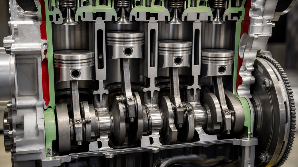
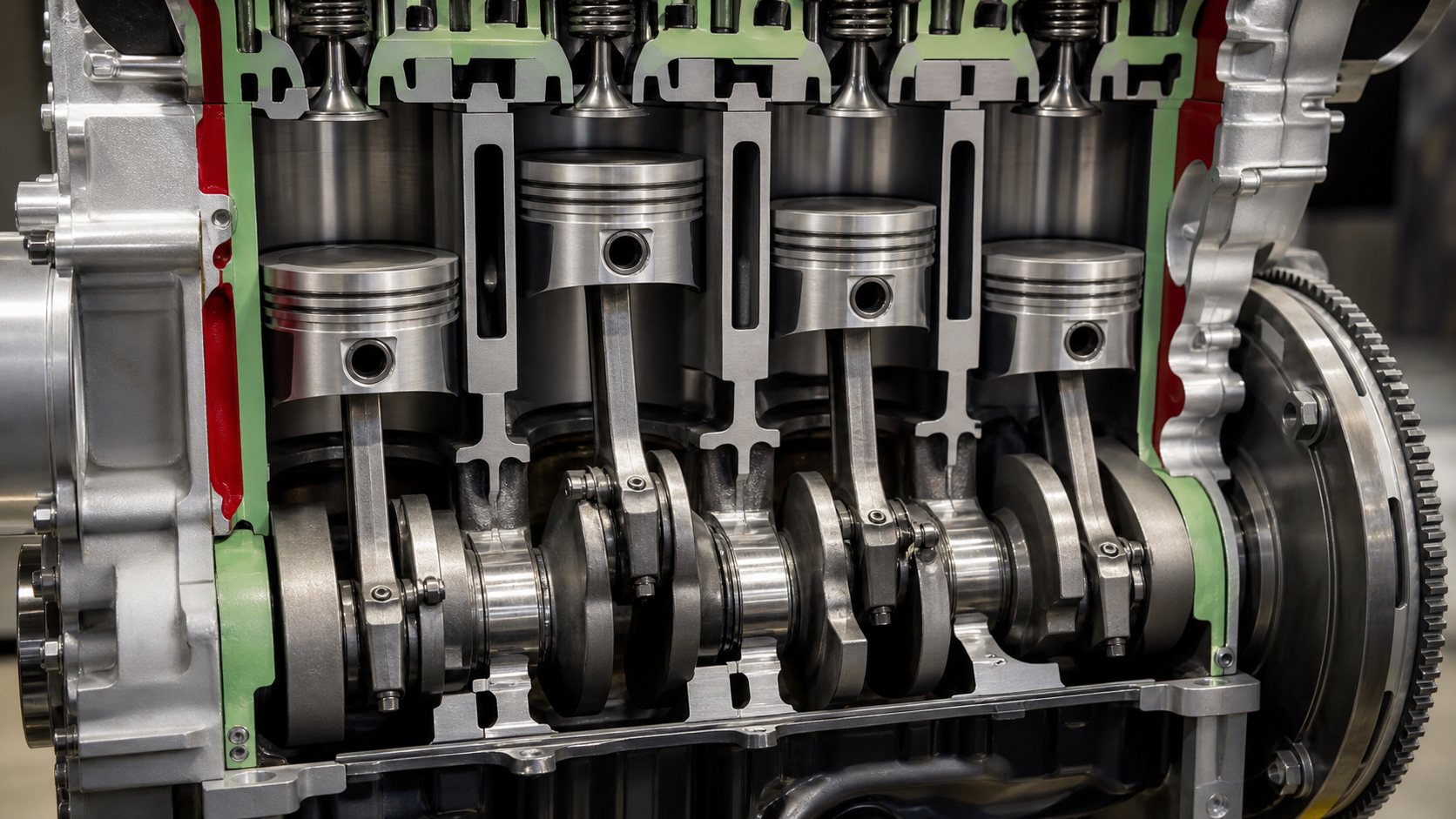
A crankshaft is a rotating shaft inside an engine that converts the reciprocating motion of pistons into continuous rotational motion. Each time combustion pressure pushes a piston down, the connecting rod transfers that force to an offset pin on the crankshaft, causing it to rotate. The crankshaft then delivers torque to the flywheel, transmission, or driven equipment. Without this conversion, the linear force from combustion would produce no usable rotation. The crankshaft’s design—its journal diameters, stroke length, counterweights, and oil supply—directly affects engine balance, durability, and power output across diesel, gasoline, and heavy-duty applications.
Key Takeaways
- The crankshaft converts linear piston force into rotation by using offset crankpins that turn each downward push into rotational torque.
- Main journals ride in block bearings and hold the crankshaft in position while crankpins connect to the piston rods and define the stroke.
- Counterweights, oil passages, and fillets work together to balance rotating mass, supply lubrication under pressure, and resist fatigue at stress concentration points.
- Thrust faces control axial movement, the nose drives accessories, and the flange mounts the flywheel or torque converter.
- Crankshaft specifications—stroke, journal diameter, fillet radius, and material—are set by the engine maker and vary with duty cycle, bore size, and intended load.
Follow the Force from Combustion to the Flywheel
When the air-fuel mixture ignites in the cylinder, pressure builds rapidly on the piston crown. That force pushes the piston down the cylinder bore, applying a load through the connecting rod to the crankpin—an offset journal on the crankshaft. Because the crankpin is positioned away from the crankshaft’s centerline, the downward push creates a moment arm that rotates the entire shaft. As the crankshaft turns, the main journals—aligned with the shaft’s center axis—remain stationary within their bearings in the engine block. The rotating assembly transfers torque through the crankshaft’s length to the flywheel mounting flange at the rear. The flywheel absorbs each power pulse, smooths the rotation, and delivers continuous torque to the transmission or driven equipment.
This conversion happens thousands of times per minute in typical operation. The crankshaft must withstand peak combustion pressures while maintaining rotational balance and supplying oil to every bearing surface. Wikipedia’s crankshaft overview describes the basic geometry, but the design limits and inspection procedures for a given engine come from the manufacturer’s service manual or machining specification.
Crankpins Turn Piston Motion into Rotation
The crankpin, also called the rod journal, is the cylindrical surface where the connecting rod’s big end bearing rides. It is offset from the crankshaft’s main axis by a distance equal to half the engine’s stroke. This offset—called the throw—determines how far the piston travels from top dead center (TDC) to bottom dead center (BDC). Stroke length directly affects engine displacement according to this relationship:
Displacement (per cylinder) = (π / 4) × bore² × stroke
Where bore and stroke are in the same unit. The crankpin throw determines the stroke dimension in this calculation.
As the crankshaft rotates, the connecting rod angle changes continuously. At TDC and BDC, the rod is nearly vertical and transmits force along its length with minimal side load. At 90 degrees of crankshaft rotation—when the crankpin is farthest from the cylinder axis—the rod angle is greatest and the side load on the piston and cylinder wall peaks. This geometry creates the reciprocating inertia loads that must be balanced by counterweights.
Crankpin diameter, surface finish, and hardness are tightly controlled. How crankshafts are manufactured explains the grinding and polishing steps that achieve the required finish. The engine manufacturer specifies allowable wear limits, out-of-round tolerances, and runout for each crankpin. If a crankpin exceeds these limits, the bearing will fail prematurely. Crankpin runout, measured with a dial indicator while the shaft rotates in V-blocks, must stay within the specification in the engine maker’s drawing.
Main Journals, Webs, and Counterweights Carry and Balance the Load
Main journals are the cylindrical bearing surfaces aligned with the crankshaft’s centerline. They ride in the main bearings installed in the engine block, holding the crankshaft in position while it rotates. The number of main journals typically equals the number of cylinders plus one in inline engines, providing a main bearing between each cylinder throw and one at each end. This arrangement minimizes bending deflection under combustion loads.
The crank webs, or crank arms, connect each main journal to its adjacent crankpin. They transmit the torque generated at the crankpin to the main journal and must resist both bending and torsional loads. Web thickness and fillet radius at the journal transitions are critical fatigue locations. A sharp corner or undercut radius concentrates stress and initiates cracks. Engine rebuilding guides often cite fillet radius as a primary inspection point during crack testing with magnetic particle or dye penetrant methods.
Counterweights are cast or forged extensions opposite the crankpins. They balance the rotating mass of the crankpin and a portion of the connecting rod’s weight, reducing vibration and bearing loads. Without counterweights, the eccentric crankpin mass would create a rotating imbalance equal to the crankpin mass times its throw radius. This imbalance generates vertical and horizontal forces that shake the engine and accelerate bearing wear.
The counterweight mass required depends on the crankpin mass, the throw, and the fraction of the connecting rod’s reciprocating mass treated as rotating. The balance factor varies by engine design. High-performance and racing engines may use external balance—where part of the counterweight mass is attached to the flywheel or harmonic damper—to reduce crankshaft length and increase torsional stiffness.
Measuring counterweight position and mass during a rebuild is essential when replacing a crankshaft or machining journals undersize. If a crankpin is ground undersize to remove a wear ridge, the reduction in crankpin diameter changes the rotating mass and may require counterweight adjustment or a different balance factor.
Oil Passages, Fillets, Thrust Faces, Nose, and Flange
Internal oil passages drilled through the crankshaft deliver pressurized oil from the main journals to the crankpins. Oil enters through a hole in the main journal, travels through a diagonal or radial passage in the web, and exits at the crankpin journal. This continuous supply forms a hydrodynamic oil film that separates the bearing surfaces. If an oil passage becomes blocked by debris or casting residue, the downstream bearing will fail due to metal-to-metal contact within seconds at operating speed.
Inspecting oil holes during reconditioning requires compressed air or solvent flushing to confirm flow. Some crankshafts have plugged cross-drilled holes that must be verified open. A missing or loose plug will drop oil pressure and starve downstream bearings. Surface finish inside the oil passage is less critical than on the bearing journals, but sharp edges at passage exits can disturb oil film formation.
Fillet radii at every journal-to-web transition act as stress relief features. The fillet—a smooth, radiused transition—spreads the bending stress over a larger area than a sharp corner. Fillet rolling or induction hardening after machining increases fatigue strength at these locations. A crankshaft that has been ground undersize must have the fillet radius recut or rolled to the correct dimension. If the fillet is too small or blends poorly into the journal, a fatigue crack will initiate there under repeated load cycles.
Thrust faces or thrust washers control the crankshaft’s axial position. Engine torque, clutch engagement, and accessory belt loads create axial forces that would shift the crankshaft forward or rearward without a thrust bearing. The thrust bearing—usually a flanged main bearing or separate thrust washer—reacts against a machined face on one of the center main journals. Excessive axial play, measured as end float or thrust clearance, indicates thrust face wear and allows the crankshaft to move enough to misalign gears or interfere with the block. The engine manufacturer specifies allowable thrust clearance. Measurement procedures use a dial indicator and pry bar to check movement.
The crankshaft nose—the front end of the shaft—drives the timing gear or chain, harmonic balancer, and accessory belts. It is usually a smaller diameter than the main journals and may have a keyway, splines, or a threaded end for mounting pulleys. The harmonic balancer absorbs torsional vibration that would otherwise fatigue the crankshaft. A damaged or missing balancer allows the crankshaft to flex torsionally at its resonant frequency, leading to fatigue cracks in the webs.
The flange at the rear of the crankshaft mounts the flywheel or flexplate. It is a flat, machined surface with bolt holes arranged in a specific pattern. Flywheel bolts are torqued to the manufacturer’s specification to clamp the flywheel without distorting the crankshaft or creating runout. If the flange face is not perpendicular to the crankshaft axis within the specified tolerance, the flywheel will wobble and cause clutch chatter or starter engagement problems.
Why Crankshaft Design Changes with Engine Duty
Crankshaft specifications differ between gasoline, diesel, and heavy-duty industrial engines because combustion pressure, speed, and duty cycle impose different loads. Diesel engines typically generate higher peak cylinder pressures than gasoline engines. This higher pressure requires larger journal diameters, thicker webs, and higher-strength materials to resist bending and fatigue. Automotive crankshaft manufacturing typically uses forged steel for diesel and performance applications, while cast iron or cast steel serves lower-stress gasoline engines.
Stroke length and rod length ratio affect piston speed and side load. A longer stroke increases mean piston speed, which raises inertia loads and bearing surface velocity. Mean piston speed is calculated as:
Mean Piston Speed = (2 × stroke × rpm) / 60,000
Where stroke is in millimeters and rpm is crankshaft revolutions per minute. Higher-speed engines require lighter pistons, stronger rods, and stiffer crankshafts to control inertia loads.
The rod-to-stroke ratio—connecting rod length divided by stroke—affects side load and dwell time at TDC. A longer rod reduces the angle between the rod and cylinder axis, decreasing side load on the piston and cylinder wall. A shorter rod allows a more compact engine but increases side load and piston acceleration. Crankshaft repair decisions must account for these differences because machining tolerances, fillet radii, and hardness requirements vary by application.
Industrial and marine crankshafts for continuous-duty engines use larger journal diameters, higher-strength alloys, and shot-peened fillets to extend fatigue life. A crankshaft designed for long inspection intervals cannot be substituted directly into an engine designed for shorter intervals without verifying material properties, fillet radii, and journal hardness.
When sourcing a replacement crankshaft, confirm the engine model, serial number, and drawing number. Many engines share bore and stroke dimensions but use different crankshaft designs due to differences in bearing size, flange bolt pattern, or counterweight configuration. A crankshaft manufacturer requires the original part number, measured journal diameters, stroke, flange dimensions, and any undersize or modification history to produce an accurate replacement. Custom applications—such as increased stroke, different rod length, or external balance—require engineering review of the connecting rod geometry, piston clearance, and block machining before manufacturing.
FAQs
Can a crankshaft be machined undersize more than once?
Each undersize grind removes material from the journal surface and reduces the journal diameter. Most engine manufacturers allow multiple undersize steps before the journal becomes too small to carry the bearing load safely. The engine’s repair manual specifies the minimum journal diameter and the available undersize bearing sets. Grinding beyond the minimum diameter risks journal flex, oil film collapse, and premature bearing failure.
How do you measure crankshaft runout?
Mount the crankshaft in V-blocks or precision centers at the outer main journals. Position a dial indicator against the center main journal with the plunger perpendicular to the journal surface. Rotate the crankshaft one full revolution and record the total indicator movement. The runout is half the total indicator reading. Compare this value to the engine maker’s specification. Excessive runout indicates a bent crankshaft that cannot be straightened reliably and must be replaced.
What causes crankshaft fillet cracks?
Fillet cracks start at the radius transition between the journal and the web due to stress concentration. Repeated bending loads from combustion pressure and inertia forces create cyclic stress at the fillet. If the fillet radius is too small, the surface finish is rough, or the material has been weakened by overheating or improper grinding, a fatigue crack will initiate and propagate. Other contributing factors include engine over-speed, detonation, and misaligned bearings that impose side loads. Magnetic particle or dye penetrant inspection will reveal surface cracks before they grow large enough to cause catastrophic failure.
Is a forged crankshaft always stronger than a cast crankshaft?
Forged crankshafts generally have higher tensile strength and better fatigue resistance than cast crankshafts because the forging process aligns the grain structure along the load path. However, modern cast crankshafts made from nodular iron or cast steel can meet the strength requirements of many gasoline engines. The choice depends on the engine’s duty cycle, peak cylinder pressure, and cost constraints. Diesel and high-performance engines require forged crankshafts, while passenger-car gasoline engines often use cast crankshafts. Billet crankshaft options offer the highest strength for racing and custom applications but require machining from solid bar stock.
Can you weld a cracked crankshaft?
Welding a cracked crankshaft is generally not recommended because the heat-affected zone around the weld changes the material’s hardness and grain structure, creating a new stress concentration. Even if the weld is ground flush and blended, the residual stress and metallurgical changes make the repair prone to re-cracking under cyclic load. The only acceptable welding repair is build-up of a worn journal surface followed by grinding to the correct diameter, and this must be done using a controlled preheat, low-hydrogen electrode, and post-weld stress relief. This process requires specialized equipment and is typically more expensive than replacing the crankshaft. Most engine builders replace a cracked crankshaft rather than attempt welding repair.
Conclusion
A crankshaft converts combustion force into rotation by using offset crankpins, balanced counterweights, and precision-machined journals that ride in pressurized oil films. Each design feature—stroke, journal diameter, fillet radius, oil passage routing, thrust face, and flange bolt pattern—is specified by the engine manufacturer based on combustion pressure, operating speed, and duty cycle. When selecting a replacement or evaluating a used crankshaft, verify the part number, measure journal diameters and runout, inspect fillets for cracks, and confirm thrust clearance against the engine maker’s specification. If machining undersize, recut the fillet radii and check counterweight balance to maintain the original rotating mass distribution.