
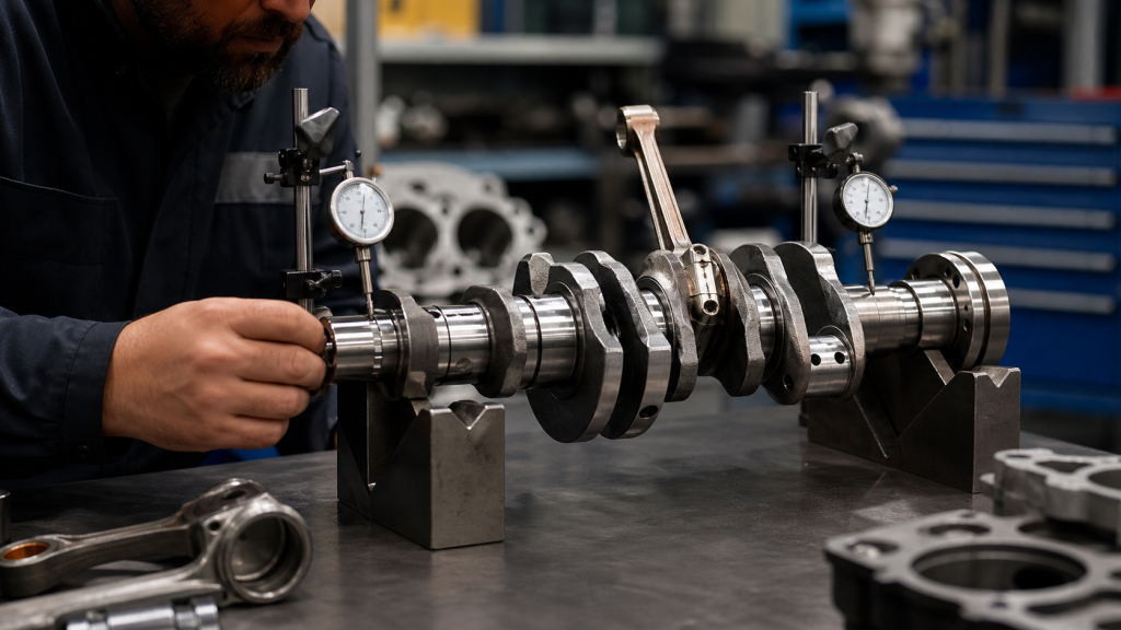
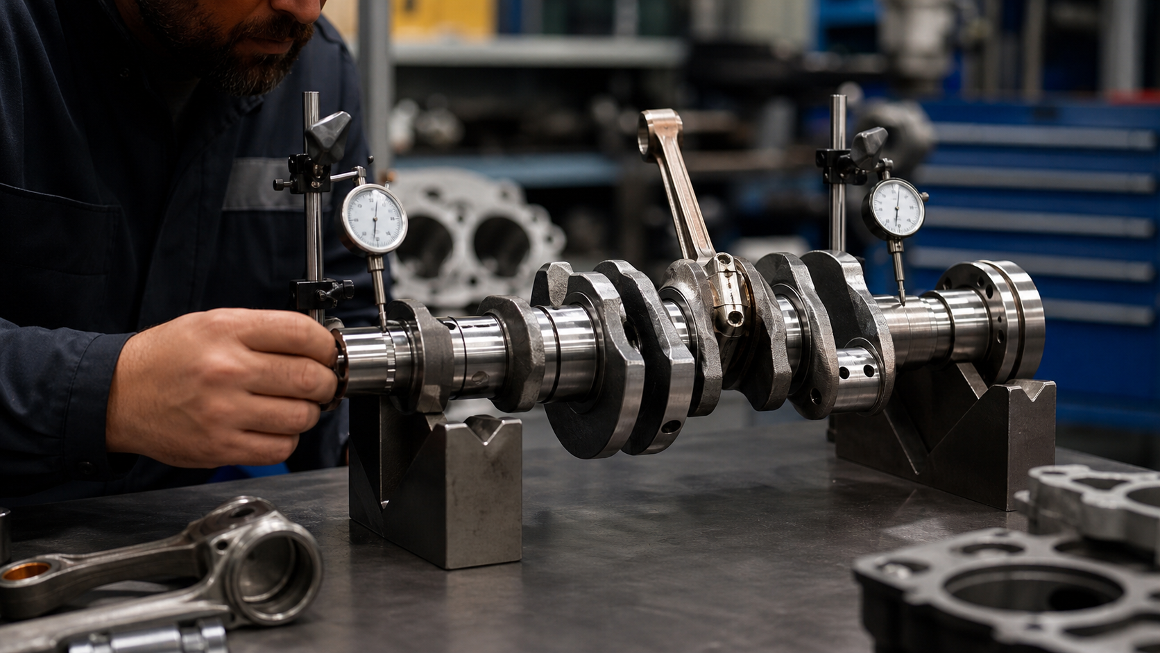
A motorcycle crankshaft converts the reciprocating motion of pistons into rotary motion while managing primary balance forces and delivering power to the transmission. Most motorcycle engines use either a pressed assembly—where crank pins press into separate flywheel halves—or a one-piece forged or cast design. The construction affects inspection access, rebuild feasibility, and replacement sourcing. Rebuilders must verify runout, journal wear, and alignment against engine-maker limits before committing to machining or replacement. Custom manufacturing requires complete dimensional data, material specifications, and validation criteria.
Key Takeaways
- Pressed crankshafts separate into flywheel halves and crank pins for inspection, enabling press-fit rebuild when components remain within tolerance.
- One-piece crankshafts require specialized measurement tooling and cannot be disassembled for internal inspection without destructive sectioning.
- Runout and journal diameter checks against engine-maker specifications determine whether regrinding, undersize bearings, or replacement is necessary.
- Balance factor, counterweight mass, and inertial axis alignment are engine-model-specific and must follow manufacturer data or dynamometer validation.
- Custom crankshaft feasibility depends on complete drawings, material certifications, forging or casting process capability, and acceptance test procedures.
One-Piece and Pressed Motorcycle Crankshaft Layouts
Pressed crankshafts dominate older parallel-twin and many single-cylinder engines. The design uses two flywheel halves, one or more crank pins, and a connecting rod assembly that installs between the flywheels before the pin is pressed into position. The press fit creates a friction joint strong enough to handle combustion loads while allowing disassembly for inspection or replacement of individual components. Standard rebuild procedures call for measuring the press-fit interference, checking each flywheel for runout and perpendicularity, and verifying that the crank pin surface has not exceeded the regrind limit.
One-piece crankshafts appear in most modern inline-four, V-twin, and high-performance engines. The entire assembly—main journals, rod journals, counterweights, and connecting webs—is forged or cast as a single component, then machined to final geometry. This construction eliminates press-fit separation risk and permits tighter journal-to-journal concentricity, but it also prevents internal inspection without sectioning. Runout, straightness, and journal wear must be measured on the assembled crankshaft, and any out-of-tolerance condition typically requires complete replacement unless the journals can be reground and undersize bearings are available.
Split crankshafts, where the main journals separate at a parting line, are rare in motorcycles but appear in some large-displacement designs. These allow crankcase installation without splitting the cases vertically, but they introduce additional joint surfaces that must be aligned and torqued per manufacturer specification.
Crankpins, Flywheels, Rods, Bearings, and Balance Factor
The crank pin supports the connecting rod’s big-end bearing and transmits combustion force to the flywheel assembly. Its surface finish, diameter tolerance, and concentricity relative to the main-journal axis determine bearing life and vibration. Engine makers specify maximum taper and out-of-round limits that vary by bearing type and engine speed. A crank pin that exceeds these limits will cause rapid bearing wear even if total runout appears acceptable on a dial indicator.
Flywheels in pressed assemblies store rotational inertia and carry counterweights to balance primary forces. The fit surfaces where the crank pin enters the flywheel must remain round and parallel; any distortion from a previous overheating event or impact will prevent proper press-fit interference and create a loose assembly. Measuring the bore diameter at multiple points with a bore gauge or inside micrometer identifies ovality or taper that would compromise the rebuild.
Balance factor defines how much of the reciprocating mass is offset by the rotating counterweights. Single-cylinder and parallel-twin engines use a balance factor that represents a compromise between primary vertical shake and rocking couple. The exact value varies by engine design and intended application. V-twin and inline-four layouts have different primary and secondary balance characteristics, and their balance factors are built into the crankshaft design rather than being field-adjustable.
Bearing clearances between the journals and the crankcase or rod depend on journal diameter, surface finish, and oil-film thickness at operating temperature. Measuring clearance with Plastigage or a dial-bore gauge and outside micrometer verifies that the oil film will remain intact under load. Excessive clearance allows journal whip and pressure loss; insufficient clearance risks seizure during thermal expansion. Consult the engine service manual for the correct clearance range for your specific bearing configuration.
Runout and Alignment Checks Before a Rebuild Decision
Runout measurement reveals whether the crankshaft is straight and whether the journals are concentric. Mount the crankshaft in V-blocks or between lathe centers, supporting it at the outer main journals. Position a dial indicator with its plunger perpendicular to the center main journal surface, then rotate the crankshaft one full turn while noting the total indicator movement. Repeat the measurement on each rod journal. Compare total runout against the engine maker’s specification to determine whether the crankshaft is acceptable, requires straightening, or must be replaced.
For pressed crankshafts, measure runout on each flywheel separately after disassembly. Place the flywheel on a surface plate with the crank-pin bore facing up, then sweep a dial indicator across the bore’s inner diameter and across the face that mates to the other flywheel half. Any wobble or face runout transfers directly into rod-journal misalignment when the assembly is pressed together. Flywheel runout exceeding the manufacturer limit means the flywheel must be trued on a lathe or replaced.
Journal diameter and taper measurements use a micrometer at multiple points along the journal length and at 90-degree intervals around the circumference. Record the readings and calculate the difference between the largest and smallest diameter. Taper or out-of-round beyond the service manual limit suggests uneven wear or lubrication starvation. If the journal diameter has worn beyond the smallest standard bearing clearance, regrinding to the next undersize is necessary, provided the journal thickness allows material removal without compromising strength.
Straightness along the entire crankshaft length can be checked by mounting between centers and measuring runout at each journal and counterweight position. A crank that shows acceptable runout at the main journals but high runout at a rod journal may have a bent throw or misaligned press fit rather than uniform bending. This condition often follows a connecting-rod failure or severe overrev event.
Measurement | Tool | Reference Source | Decision Point |
|---|---|---|---|
Total runout, main journals | Dial indicator on V-blocks | Service manual | Replace or straighten if exceeded |
Rod journal taper | Outside micrometer, multiple points | Service manual | Regrind if beyond limit |
Flywheel face runout | Dial indicator on surface plate | Service manual | True or replace if exceeded |
Journal diameter wear | Micrometer at multiple angles | Bearing clearance specification | Regrind if below minimum |
Always consult the engine-specific service manual for exact limits. The table outlines the measurement approach and decision logic, but actual tolerance values depend on the engine model, bearing design, and operating conditions.
When Rebuilding Is Feasible and When Replacement Is Safer
Rebuilding a pressed crankshaft is feasible when the flywheel bores remain round and within interference-fit diameter, the crank pin can be reground to a standard undersize, and the main journals do not exceed runout or taper limits. The typical rebuild sequence includes pressing the assembly apart, inspecting each component, regrinding worn journals, replacing the crank pin if its diameter has dropped below the smallest undersize, and pressing the assembly back together with new or trued flywheels. Interference fit on reassembly must match or exceed the original specification to prevent loosening under load.
Rebuilding becomes uneconomical or unsafe when the flywheel bores have ovalized beyond the manufacturer limit, the crank pin has visible cracks in the fillet radius, or the main journals have been reground past the last undersize bearing availability. Some engines offer bearings in multiple undersizes, while others provide limited regrind options. Once the journal diameter requires more material removal than the thinnest available bearing allows, replacement is the only option unless custom bearings can be sourced and validated.
One-piece crankshafts present a simpler decision boundary. If the journals are within standard or available undersize limits, the crankshaft is straight within specification, and no cracks are visible under magnetic-particle or dye-penetrant inspection, regrinding and undersize bearings restore service life. If any journal exceeds the last undersize, if the crankshaft is bent beyond the straightening capability of the machine shop, or if cracks appear in the fillets or counterweight roots, replacement is mandatory. Attempting to weld-repair a cracked crankshaft or straighten a severely bent one introduces residual stress and fatigue risk that standard inspection cannot detect.
Fatigue cracks usually initiate at fillet radii where the journal transitions to the counterweight or web. These high-stress regions concentrate bending loads during every power stroke, and any surface defect, corrosion pit, or machining mark becomes a crack nucleation site. Magnetic-particle inspection after degreasing and before any machining operation reveals surface-breaking cracks that are invisible to the naked eye. Fluorescent dye-penetrant inspection works for non-ferrous materials like some aluminum flywheels, though steel crankshafts are far more common in motorcycles.
Data Required for a Custom-Manufacturing Feasibility Review
Custom crankshaft manufacturing for a motorcycle engine begins with a complete dimensional drawing that defines every journal diameter, stroke length, journal width, fillet radius, counterweight profile, keyway or taper location, and center-to-center distance. The drawing must include geometric dimensioning and tolerancing (GD&T) callouts for runout, perpendicularity, concentricity, and surface finish. Without these details, the manufacturer cannot program CNC machining operations or set up inspection fixtures that verify acceptance criteria.
Material specification follows the drawing. Most motorcycle crankshafts use forged steel alloys such as SAE 1045, 4140, or 4340, each with distinct hardenability, tensile strength, and fatigue resistance. Forged construction offers superior grain flow and impact strength compared to cast iron or nodular iron, which appear in some older or low-performance designs. The material certification must state the heat-treatment condition—normalized, quenched and tempered, or induction-hardened journals—because post-forging thermal processing controls hardness, ductility, and residual stress. A custom order without a specified material or heat treatment cannot be quoted or validated.
Balance requirements include the total rotating weight, reciprocating weight, balance factor, and counterweight position relative to each throw. Some engines use external bolt-on counterweights or a separate balance shaft; these components must be documented so the crankshaft manufacturer can verify that the primary and secondary forces meet the engine maker’s vibration limits. Omitting balance data leads to a crankshaft that is dimensionally correct but dynamically unsuitable.
Acceptance criteria define the inspection plan and final quality gate. Typical requirements include maximum total indicated runout, journal diameter tolerance, surface finish in microinches Ra, hardness range on journals and fillets, and non-destructive testing method. Magnetic-particle or ultrasonic inspection detects internal defects that dimensional measurement cannot reveal. A feasibility review assesses whether the requested tolerances, surface finish, and inspection protocol match the manufacturer’s process capability and whether the production volume justifies tooling investment.
Production volume affects both tooling cost and per-piece price. A single prototype may require manual setup and conventional machining, while larger production runs justify dedicated CNC programs, forging dies, and automated inspection fixtures. Lead time scales with complexity; a simple single-cylinder crankshaft with two main journals and one rod journal may be completed relatively quickly, while a multi-cylinder design with offset throws and complex counterweights requires additional time for tooling development and first-article validation.
Understanding how crankshafts are manufactured helps when preparing specifications for custom orders. The process sequence—forging, rough machining, heat treatment, finish grinding, and inspection—applies across different crankshaft types, but motorcycle designs often demand tighter tolerances and more aggressive fillet radii due to higher specific speeds. Reviewing these process details during the RFQ phase prevents later discovery that a requested feature exceeds standard capability.
FAQs
Can a pressed crankshaft be rebuilt more than once?
Yes, provided the flywheel bores remain within interference-fit diameter and round, and the crank pin has not been reground past the last available undersize. Each rebuild removes material from the pin during regrinding, so the practical rebuild limit depends on how much diameter remains above the smallest bearing size. Most pins allow multiple regrinds before replacement is necessary, though the exact number depends on the initial journal diameter and available undersize bearing range.
How does counterweight position affect engine vibration?
Counterweights offset the rotating and reciprocating masses to reduce primary vertical shake and rocking couple. Single-cylinder engines balance a specific percentage of the reciprocating weight, creating a compromise between up-down vibration and side-to-side rocking. The balance factor is determined by the engine designer based on intended use, displacement, and acceptable vibration levels. Changing counterweight mass or position without engine-maker data or dynamometer testing can shift the vibration peak to a different RPM range or increase overall vibration amplitude.
What causes a crankshaft to bend during operation?
Bending usually follows a connecting-rod failure, hydraulic lock from ingested water, or severe overrev that exceeds the design speed limit. The sudden load spike from a broken rod or impact with the piston crown bends the crankshaft journals out of alignment. Once bent, the crankshaft cannot be reliably straightened unless the deflection is very small and the shop has a hydraulic press and dial-indicator setup to measure cold-set correction incrementally.
Are billet crankshafts stronger than forged crankshafts for motorcycles?
Billet crankshafts machined from solid bar stock offer tighter tolerances and custom geometry but lack the grain-flow directionality that forging creates. Forged crankshafts align the metal grain structure with the stress paths, improving fatigue resistance in the fillets and webs. For racing or high-output applications, forged cranks generally outperform billet unless the billet material is a high-strength alloy and the design includes generous fillet radii.
What inspection confirms a used crankshaft is safe to reuse?
Measure runout at all journals, check journal diameter and taper with a micrometer, inspect fillet radii for cracks using magnetic-particle or dye-penetrant methods, and verify that all oil passages are clear and not scored. Compare the measurements against the engine-maker limits. If every parameter is within tolerance and no cracks appear, the crankshaft can be reused with standard bearings or reground to the next undersize if wear is present. Crankshaft repair decisions depend on measured condition rather than age or appearance alone.
Conclusion
Motorcycle crankshaft decisions hinge on measured geometry, construction type, and engine-maker limits rather than visual assessment or generic rebuild advice. Pressed assemblies allow component-level inspection and press-fit rebuild when flywheel bores and crank pins remain within tolerance; one-piece designs simplify alignment but require complete replacement when journals exceed undersize limits or cracks appear. Runout and journal measurements with dial indicators and micrometers establish whether regrinding or replacement is necessary. Custom manufacturing requires complete dimensional drawings, material certifications, balance data, and acceptance criteria before feasibility and lead time can be assessed. Start with the engine service manual or casting numbers to retrieve the correct limits, then measure every journal and fillet before committing to machining or ordering a replacement.