
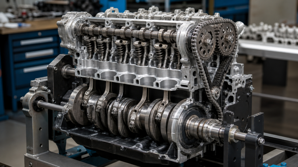
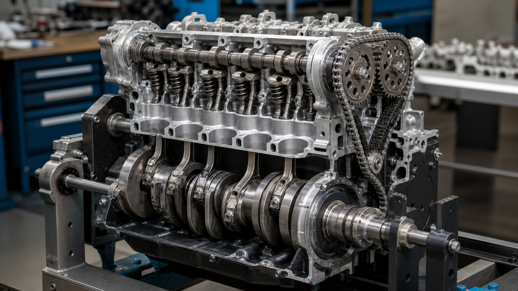
When you remove a timing cover and check the alignment marks between the crankshaft and camshaft gears, you see the mechanical proof of how these two shafts work together. The marks line up at a specific ratio—two full crankshaft rotations for every one camshaft rotation—because a four-stroke engine demands that timing relationship. The crankshaft converts combustion force into rotation at the bottom of the engine. The camshaft uses that rotation to open and close valves at the top, but at exactly half the speed. Understanding this 2:1 coupling and what each shaft does helps you diagnose which component has failed when symptoms appear.
Key Takeaways
- The crankshaft rotates at engine speed and converts reciprocating piston motion into rotational power; the camshaft rotates at half that speed and controls valve timing through cam lobes.
- Timing chains, belts, or gears maintain the 2:1 speed ratio between the shafts, and timing component failure can cause valve-to-piston contact in interference engines.
- The crankshaft position sensor (CKP) tracks piston location for ignition timing; the camshaft position sensor (CMP) identifies valve timing for fuel injection sequencing.
- Crankshaft failures produce catastrophic knocking and typically prevent engine operation; camshaft failures cause rough idle, valve train noise, and power loss while the engine still runs.
- Correlation code P0016 indicates the timing relationship between the shafts is incorrect, pointing to timing system wear or misalignment rather than sensor failure.
What Each Shaft Does: Location and Core Function
Crankshaft Job: Converting Combustion Force to Rotation
The crankshaft sits in the bottom end of the engine block, supported by main bearing journals that allow it to rotate. Connecting rods attach to offset crankpins, creating the throw that converts the up-and-down motion of pistons into continuous rotation. During the power stroke, combustion pressure pushes the piston down, driving the connecting rod against the crankpin and forcing the crankshaft to rotate. Counterweights built into the crankshaft design balance these reciprocating forces.
The crankshaft drives everything downstream: the transmission through the flywheel or flexplate, engine accessories through the front pulley and belt system, and the camshaft through the timing system. Every component that requires rotational power from the engine receives it from the crankshaft. As the research from MechContent confirms, the crankshaft also powers the fuel pump, coolant pump, and air conditioning compressor in many engine configurations.
Camshaft Job: Opening and Closing Valves on Schedule
The camshaft operates in the top end of the engine—either in the cylinder head (overhead cam) or in the engine block (overhead valve with pushrods). Cam lobes machined onto the shaft have precisely shaped profiles that determine when valves open, how far they open, and how long they stay open. As each lobe rotates past its corresponding valve lifter or rocker arm, the lobe’s raised section pushes the valve open against spring pressure. When the base circle of the lobe returns, the valve spring closes the valve.
Single overhead cam (SOHC) engines use one camshaft per cylinder head to operate both intake and exhaust valves. Dual overhead cam (DOHC) engines use separate camshafts for intake and exhaust valves, allowing more precise control over valve timing and higher engine speeds. According to Family Handyman, some engines use up to four camshafts in V-configuration designs—two per cylinder bank.
The camshaft receives all its power from the crankshaft through the timing system. It produces no power itself; it only distributes the rotation it receives to control airflow through the engine.
Why the 2:1 Speed Ratio Matters: Timing System Coupling
The Four-Stroke Cycle Demands Half-Speed Cam Rotation
A four-stroke engine completes one power cycle in 720 degrees of crankshaft rotation—two full revolutions. During those two revolutions, each cylinder goes through four distinct strokes:
- Intake stroke (0-180°): Intake valve opens, piston moves down, air-fuel mixture enters cylinder
- Compression stroke (180-360°): Both valves closed, piston moves up, mixture compressed
- Power stroke (360-540°): Both valves closed, spark ignites mixture, piston driven down
- Exhaust stroke (540-720°): Exhaust valve opens, piston moves up, burned gases expelled
Each intake valve opens once during this 720-degree cycle—at the start of the intake stroke. Each exhaust valve opens once—at the start of the exhaust stroke. As MechBasic explains, the camshaft rotates at half the speed of the crankshaft because each valve opens once every two crankshaft revolutions. If the camshaft rotated at full engine speed, valves would open twice per cycle, destroying the four-stroke sequence.
This 2:1 ratio is not adjustable or approximate. It is a mechanical constant enforced by the timing system. The camshaft completes exactly 360 degrees while the crankshaft completes 720 degrees.
How Timing Chains, Belts, and Gears Connect the Shafts
The timing system uses sprockets on both the crankshaft and camshaft connected by a chain, belt, or in some older engines, directly meshing gears. The camshaft sprocket has twice the diameter (twice the number of teeth) of the crankshaft sprocket. When the crankshaft sprocket completes two full rotations, the camshaft sprocket completes one.
Timing chains run inside the engine, lubricated by engine oil. They use metal links that engage with sprocket teeth. Chain tensioners maintain proper tension as the chain wears. Timing chains typically outlast timing belts and may last the life of the engine in well-maintained vehicles, though they can stretch over time, causing timing drift.
Timing belts run outside the main engine block under a protective cover. Made from reinforced rubber with toothed profiles, they require replacement at manufacturer-specified intervals, which vary by engine design and operating conditions. Belts fail suddenly when the rubber degrades or teeth strip.
Gear-driven timing uses direct gear-to-gear contact, most common in older pushrod engines and some diesel applications. This system is the most durable but generates more noise and friction than chains or belts.
The timing system also includes guide rails or idler sprockets that route the chain or belt, plus tensioners that compensate for wear and maintain the correct relationship between the shafts. When any timing component fails, the 2:1 ratio is lost immediately.
What Happens When Timing Components Fail
In non-interference engines, the piston never occupies the same space as a fully open valve, even at top dead center. If the timing belt breaks or the chain jumps several teeth, the valves stop moving but the pistons continue. The engine stops running but sustains no internal damage. You replace the timing component and restart.
In interference engines, valve and piston paths overlap. The camshaft timing prevents collision by ensuring valves are closed when the piston reaches top dead center. If timing is lost, open valves extend into the piston’s path. When the crankshaft continues rotating, pistons strike valve heads, bending valves, damaging pistons, and sometimes breaking connecting rods. The engine requires complete top-end rebuild.
Before catastrophic failure, timing problems create measurable symptoms. A stretched timing chain retards cam timing by a few degrees, causing rough idle, hesitation, and reduced power. The engine computer may set code P0016 (crankshaft/camshaft position correlation), indicating the sensors detect incorrect timing relationship. This code means the timing system components have worn or shifted—the sensors themselves are working correctly and reporting what they see.
How Sensors Track Each Shaft for ECU Control
Crankshaft Position Sensor: Tracking Piston Location
The crankshaft position sensor (CKP) mounts near the crankshaft, aimed at a toothed reluctor wheel or tone ring attached to the crankshaft. As the crankshaft rotates, the teeth pass the sensor, generating a voltage pulse pattern. The engine control unit (ECU) reads this pattern to determine crankshaft speed and exact piston position.
The ECU uses CKP data primarily for ignition timing. To fire the spark plug at the correct moment before top dead center on the compression stroke, the ECU must know exactly where the crankshaft is at any instant. The CKP signal provides that information in real time. The reluctor wheel typically has a missing tooth or reference gap that identifies the starting point, allowing the ECU to count from a known position.
When the CKP sensor fails, the ECU cannot determine piston position. Common diagnostic trouble codes include:
- P0335: Crankshaft Position Sensor "A" Circuit malfunction
- P0336: Crankshaft Position Sensor "A" Circuit Range/Performance
CKP failure symptoms include no-start conditions (engine cranks but won’t fire), stalling at idle or while driving, rough running with intermittent misfires, and inability to accelerate smoothly. Some vehicles will not even attempt to crank if the ECU receives no CKP signal.
Camshaft Position Sensor: Identifying Valve Timing
The camshaft position sensor (CMP) works similarly to the CKP but tracks camshaft rotation instead. It mounts near the camshaft (cylinder head area) and reads a reluctor pattern on the camshaft gear or sprocket. While the CKP tells the ECU where the pistons are, the CMP tells the ECU which cylinder is on its intake stroke.
The ECU uses CMP data primarily for fuel injection sequencing. In sequential fuel injection systems, each injector fires at a specific time relative to its cylinder’s intake stroke. The CMP signal allows the ECU to identify which cylinder is next in the firing order and inject fuel accordingly. Without CMP data, the ECU may switch to batch-fire mode (firing multiple injectors at once) or use the CKP signal alone with reduced precision.
Common CMP diagnostic codes include:
- P0340: Camshaft Position Sensor "A" Circuit malfunction (Bank 1)
- P0341: Camshaft Position Sensor "A" Circuit Range/Performance (Bank 1)
CMP failure symptoms include hard starting (extended cranking), rough idle, poor fuel economy, misfires under load, and illuminated check engine light. Unlike CKP failure, CMP failure rarely prevents the engine from running—it just runs poorly with reduced efficiency.
Correlation Code P0016: When Timing Is Wrong
Code P0016 ("Crankshaft Position – Camshaft Position Correlation Bank 1 Sensor A") indicates the ECU sees a timing mismatch between the two sensors. Both sensors are functioning and sending signals, but the signals show the camshaft is not where it should be relative to the crankshaft position.
Common causes include:
- Stretched or worn timing chain allowing cam timing drift
- Jumped timing belt (belt skipped one or more teeth)
- Incorrect timing component installation after repair
- Worn timing chain tensioner or guide rails
- Cam phaser malfunction (in variable valve timing systems)
This code tells you to inspect the timing system mechanically, not replace sensors. The sensors are reporting accurately—the problem is the physical relationship between the shafts has changed.
How to Tell Which Shaft Has Failed: Symptom Patterns
Crankshaft Failure Symptoms
Crankshaft failures are catastrophic and usually sudden. The forces involved—combustion pressure transmitted through connecting rods at high RPM—create dramatic symptoms when the crankshaft structure fails:
Heavy knocking or banging from the bottom end of the engine indicates bearing failure or crankshaft journal damage. This sound is distinctly lower-pitched and louder than valve train noise. It often increases with RPM and may synchronize with engine speed.
Engine seizure or inability to rotate by hand suggests the crankshaft has broken, seized in its bearings, or welded to a bearing surface due to lubrication failure. The starter motor may click or grind but cannot turn the engine.
Severe vibration at all engine speeds, worse than typical imbalance, suggests crankshaft damage has created asymmetric rotating mass. Unlike camshaft issues that affect individual cylinders, crankshaft problems affect the entire engine’s rotation.
Metal contamination in the oil—visible as glittering particles in the oil or on the dipstick—indicates bearing material or crankshaft surface has failed and is circulating through the lubrication system.
No-start with fuel smell combined with no compression in multiple cylinders suggests catastrophic internal damage. The engine cranks (crankshaft physically turns) but cannot build compression due to broken internal components.
Crankshaft failures require immediate engine shutdown. Continued operation typically transforms a repairable crankshaft issue into complete engine destruction as debris circulates and secondary failures cascade through the bottom end.
Camshaft Failure Symptoms
Camshaft failures develop progressively and allow continued engine operation, though with deteriorating performance:
Valve train ticking or tapping from the cylinder head area indicates worn cam lobes, collapsed lifters, or excessive valve lash. This noise is higher-pitched than crankshaft knock and may be loudest at idle, quieter under load. Individual cam lobe wear creates noise on specific cylinders.
Rough idle with misfire codes suggests one or more cam lobes are not opening valves fully, creating unequal cylinder contribution. The engine shakes at idle and may smooth out slightly at higher RPM as other cylinders compensate.
Loss of power, especially in the upper RPM range, indicates inadequate valve lift or timing. Worn cam lobes reduce valve opening height and duration, restricting airflow at higher engine speeds where flow demands are greatest.
Check engine light with CMP codes (P0340, P0341) or cylinder-specific misfire codes points to cam-related timing problems rather than mechanical damage, though the root cause may still be camshaft wear.
Engine continues running is the key distinction. A vehicle with camshaft damage can often be driven to a repair facility—though this is not recommended—while crankshaft damage typically leaves you stranded or causes immediate catastrophic failure.
The diagnosis decision when facing valve train noise or performance issues is to perform a compression test and leak-down test. Low compression on specific cylinders with leak-down revealing air escaping through the intake or exhaust indicates valve sealing problems potentially caused by camshaft wear. Oil analysis showing elevated iron or chromium content confirms accelerated camshaft lobe or lifter wear.
Diagnostic Decision Tree
When symptoms appear, follow this logic:
No-start with no mechanical noise → Check CKP sensor signal with scan tool. If no signal, test CKP sensor wiring and sensor itself. If CKP signal present but engine won’t start, check CMP sensor and verify fuel delivery.
No-start with unusual mechanical noise or binding → Do not continue cranking. Remove spark plugs and attempt to rotate crankshaft by hand using a socket on the front bolt. If crankshaft rotates smoothly, inspect timing system for belt/chain failure. If crankshaft will not rotate, suspect internal mechanical failure—seized bearings, broken crankshaft, or valve-to-piston contact.
Rough idle with valve train noise → Check engine oil level and condition first. Perform compression test to identify weak cylinders. Use stethoscope to locate noise source. Inspect cam lobes through oil filler or valve cover. Check valve lash if adjustable. Suspect camshaft or lifter wear.
Catastrophic knocking during operation → Shut down immediately. Check oil level. If oil is present, suspect bearing failure or crankshaft damage. Do not restart. Tow to repair facility.
P0016 code with rough running → Verify code is not intermittent. Inspect timing chain/belt condition and tensioner operation. Check cam timing alignment marks. Measure timing chain stretch if possible. Suspect timing system wear, not sensor failure.
Progressive power loss without noise → Test fuel delivery and ignition systems first. If those are normal, perform compression test. Low compression on multiple cylinders with leak-down showing intake/exhaust valve leakage suggests camshaft lobe wear reducing valve lift.
Crankshaft vs Camshaft: Side-by-Side Comparison
Aspect | Crankshaft | Camshaft |
|---|---|---|
Location | Engine block bottom end, main bearing saddles | Cylinder head (OHC) or engine block (OHV) |
Primary Function | Convert reciprocating motion to rotation | Control valve opening/closing timing and lift |
Speed Ratio | Full engine speed (1:1 with RPM) | Half engine speed (1:2 ratio with crankshaft) |
Motion Type | Continuous rotation with offset throws | Rotation with eccentric cam lobes |
Sensor Type | CKP sensor reads reluctor for piston position | CMP sensor reads reluctor for valve timing |
Common Materials | Forged or cast steel, heat-treated bearing surfaces | Cast iron or steel, surface-hardened lobes |
Typical Wear Patterns | Bearing journal scoring, journal out-of-round | Cam lobe wear (flattening), base circle wear |
Failure Urgency | Immediate—catastrophic with severe damage risk | Progressive—degrades performance before failure |
Repair Complexity | Requires full engine disassembly, bearing work | Often accessible through valve cover or head removal |
FAQs
Can you drive with a bad camshaft?
You can physically drive a vehicle with camshaft wear or damage, but you should not. A worn camshaft creates rough idle, reduced power, and increased fuel consumption. More importantly, continued operation with a damaged camshaft can cause secondary damage—collapsed lifters may score cam journals, broken camshaft pieces can jam in the timing chain, or severely worn lobes can allow valve float that damages valve train components. The engine will continue running with significant camshaft damage, unlike crankshaft failure which stops the engine immediately, but each mile driven increases repair cost. Diagnosis and repair should happen as soon as rough running or valve train noise appears.
What is the relationship between crankshaft and camshaft speed?
The camshaft rotates at exactly half the crankshaft speed in all four-stroke engines—a fixed 1:2 ratio. This relationship is mechanically enforced by the timing system using a 2:1 gear ratio. When the crankshaft sprocket has 20 teeth, the camshaft sprocket has 40 teeth. Two full crankshaft rotations (720 degrees) produce one camshaft rotation (360 degrees). This ratio matches the four-stroke cycle requirement that each valve opens once per two crankshaft revolutions. The ratio is not adjustable except in variable valve timing systems, which shift cam timing phase by a few degrees but do not change the 2:1 speed relationship itself.
How do I know if my crankshaft sensor or camshaft sensor is bad?
Scan for diagnostic trouble codes first. Codes P0335/P0336 indicate crankshaft position sensor issues; codes P0340/P0341 indicate camshaft position sensor problems. Symptom patterns also differentiate them: CKP failure typically prevents starting—the engine cranks but will not fire, or may not even crank depending on the control system design. CMP failure allows the engine to start and run but causes rough idle, extended cranking before start, poor fuel economy, and reduced performance. You can verify sensor operation with a scan tool that displays live data—watch the CKP and CMP signals while cranking. A functioning sensor shows a cycling signal matching shaft rotation. However, if you see code P0016 (correlation error), both sensors are working—the problem is mechanical timing system wear or misalignment, not sensor failure.
What happens if the timing belt breaks?
The outcome depends on whether the engine is an interference or non-interference design. In a non-interference engine, pistons and valves occupy separate space at all times. Belt failure stops cam rotation, leaving some valves open, but pistons do not contact them. The engine stops running but sustains no internal damage. You install a new belt and restart. In an interference engine, valve and piston paths overlap, relying on correct timing to prevent collision. When the belt breaks, the camshaft stops but the crankshaft continues rotating due to momentum. Open valves extend into the cylinder space as pistons reach top dead center, causing valves to bend, pistons to crack, and occasionally connecting rods to break. Repair requires cylinder head rebuild or replacement, new pistons, and sometimes complete short block replacement. Most modern aluminum-head engines are interference designs, making timing belt maintenance according to the manufacturer’s schedule critical.
What crankshaft design features improve durability in high-stress applications?
Forged crankshafts offer superior strength compared to cast designs because the forging process aligns the steel’s grain structure with the stress paths—along the main journals and through the connecting rod throws. This orientation resists bending and fatigue. Material selection matters significantly—alloy steels provide the necessary tensile strength and fatigue resistance for demanding applications. Heat treatment processes including induction hardening of bearing surfaces increase surface hardness while maintaining a tough core, improving bearing wear resistance. Crankshaft counterweight design must balance reciprocating forces precisely; inadequate counterweighting creates vibration that accelerates bearing wear and can crack the crankshaft at stress concentration points. Fillet radius at the transition between main journals and crankpins must be smooth and large enough to prevent stress risers—sharp corners initiate fatigue cracks. Finally, cross-drilled oil passages that channel lubrication from main bearings to rod bearings must be properly chamfered and positioned to maintain maximum journal wall thickness. Refer to the engine manufacturer’s specifications or consult a specialized crankshaft manufacturer for the correct material grades and heat treatment requirements for your application.
Conclusion: Two Shafts, One Precisely Timed System
The 2:1 speed relationship between the crankshaft and camshaft is the fundamental organizing principle of four-stroke engine operation. The crankshaft converts combustion energy to rotation at full engine speed while the camshaft uses that rotation at half-speed to control valve events with precise timing. When diagnosing engine problems, understanding this relationship allows you to distinguish bottom-end crankshaft failures—catastrophic, sudden, and preventing operation—from top-end camshaft failures that create progressive performance degradation while the engine continues running. The timing system that couples these shafts is equally critical; timing component wear or failure destroys the mechanical relationship both sensors report, generating correlation codes even when the sensors function correctly.
Your next diagnostic step when facing symptoms is to categorize them: no-start with mechanical issues points to crankshaft or timing system failure, while rough running with valve noise points to camshaft wear. Use compression testing, leak-down testing, and oil analysis to verify the diagnosis before committing to repair. For crankshaft replacement in demanding applications, consult the OEM specifications or work with a qualified crankshaft supplier to ensure the replacement shaft matches the required material grade, forging process, and heat treatment standards.