
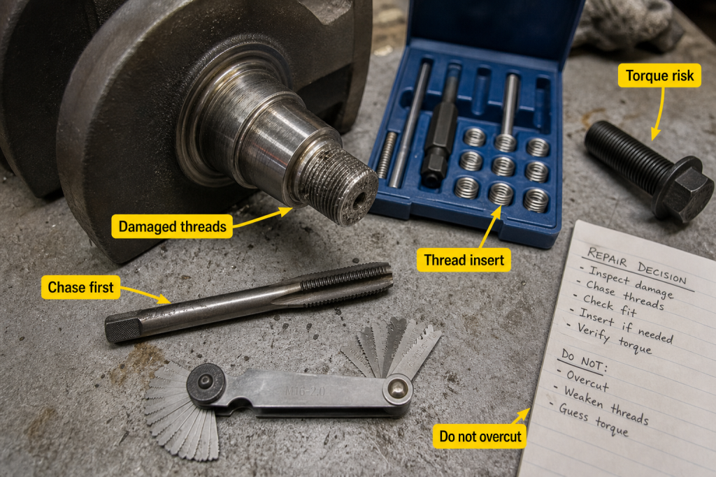
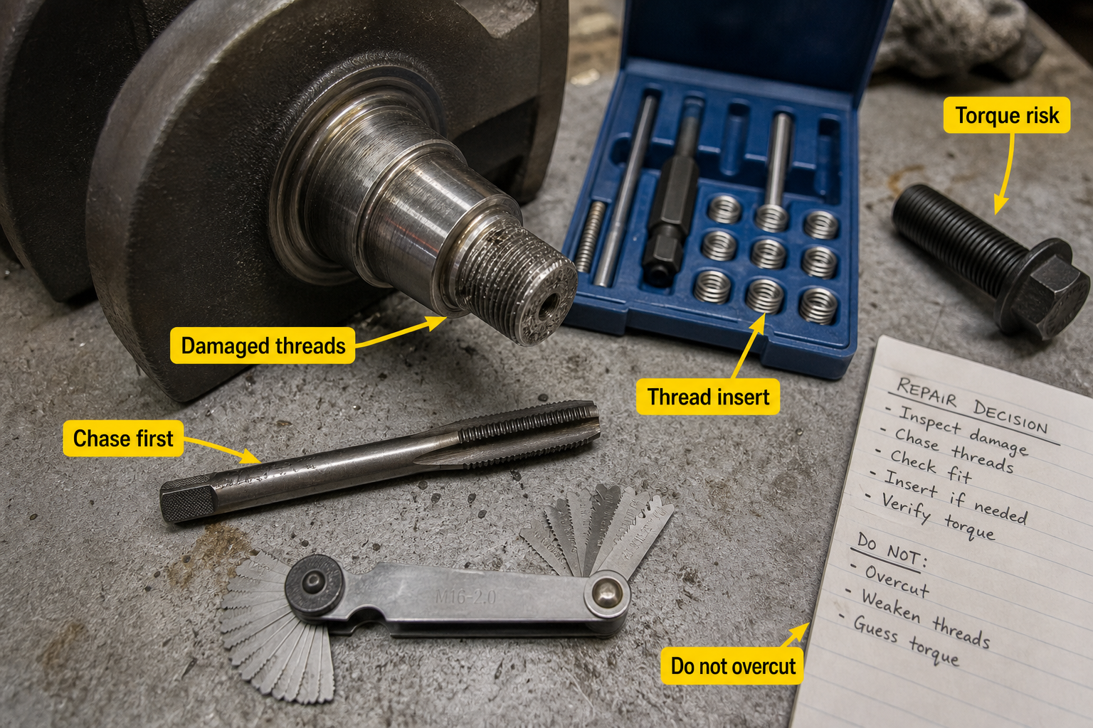
A marine diesel rebuild shop stripped the flywheel bolt threads on a forged steel crankshaft during torque-to-yield installation. The engine builder faced a choice: chase the threads with a bottoming tap, install oversized inserts, attempt a precision weld repair, or scrap a $3,800 crankshaft. Thread damage on crankshafts requires immediate evaluation because bolt torque retention, concentricity, and fatigue resistance depend on thread geometry that cannot tolerate improvisation.
Crankshaft thread repair uses thread chasing for minor damage, threaded inserts for stripped holes, and controlled welding for specific applications—but only when inspection confirms the shaft retains dimensional tolerances, has no cracks extending from the thread roots, and operates within the repaired thread’s load rating. Replacement is required when heat treatment is compromised, journal runout exceeds specification after repair, or the damaged threads serve safety-critical fasteners such as harmonic balancer or flywheel bolts in applications with liability exposure.
Key Takeaways
Thread chasing restores damaged threads without removing base material when fewer than two full threads are affected and the crest damage does not exceed 0.010 inches radially. This method preserves thread engagement length and does not introduce foreign materials.
Threaded inserts provide full-strength repair for stripped holes but reduce the effective thread length by the insert wall thickness and require precise bore alignment to prevent side loading on the crankshaft journal axis. Inserts work best on accessory bolt holes rather than primary load-bearing threads.
Welding crankshaft threads introduces heat-affected zones that alter the shaft’s heat treatment, requires post-weld machining to restore thread geometry, and mandates magnetic particle inspection to verify no cracks propagated during cooling. Most engine builders avoid welding on nitrided or induction-hardened shafts.
Assessing Thread Damage Before Choosing a Repair Method
Inspect thread damage with a thread pitch gauge and depth micrometer before selecting a repair method. Measure the remaining thread depth at the damaged section and compare it to an undamaged thread on the same shaft. If thread depth loss exceeds 25% of the original thread height, chasing will not restore adequate engagement.
Check for cracks at thread roots using magnetic particle inspection or dye penetrant testing. Cracks extending perpendicular to the thread helix indicate fatigue damage or impact loading that compromised the base material. These cracks disqualify the shaft from repair regardless of thread condition.
Verify journal runout with a dial indicator mounted on V-blocks. If total indicator runout exceeds 0.002 inches on adjacent journals, thread repair may not resolve the underlying shaft distortion. Measuring runout before and after repair confirms whether the repair process introduced additional stress or warping.
Thread Chasing for Minor Damage
Thread chasing uses a cutting tap or thread chaser to remove burrs and realign deformed threads without cutting new material. This method works when the thread roots remain intact and only the crests show peening or galling from cross-threading or impact.
Select a bottoming tap or thread chaser that matches the original thread pitch exactly. Lubricate the tool with cutting oil and turn it by hand through the damaged section, applying minimal forward pressure. Back out the tap every half turn to clear chips and prevent binding.
After chasing, test thread engagement with a new bolt of the correct grade. The bolt should thread smoothly without binding and require normal torque values to seat. If the bolt feels loose or strips under half the specified torque, the threads are too damaged for chasing and require insert repair.
Threaded Insert Repair for Stripped Holes
Threaded inserts such as Helicoil, Time-Sert, or Keensert systems restore thread strength by replacing the damaged internal threads with a precision coil or solid bushing. The repair requires drilling out the damaged threads, tapping an oversized hole, and installing the insert with thread-locking compound.
Drill the damaged hole to the insert manufacturer’s specified tap drill size, maintaining concentricity with the original bore axis. Use a drill press or boring bar mounted to the crankshaft to prevent angular misalignment. Tap the oversized hole with the insert-specific tap, using cutting fluid and frequent chip clearing.
Install the insert using the manufacturer’s installation tool, seating it 0.005 to 0.010 inches below the surface to allow for bolt head contact without interference. Apply medium-strength thread-locking compound to the external threads of the insert before installation, but avoid thread locker on the internal threads where the bolt will seat.
Insert Type | Wall Thickness | Torque Recovery | Best Application |
Helicoil (wire coil) | 0.015-0.020 in | 100-110% original | Accessory bolts, sensor bosses |
Time-Sert (solid bushing) | 0.030-0.040 in | 110-125% original | High-load fasteners, flywheel bolts |
Keensert (locking collar) | 0.025-0.035 in | 105-115% original | Vibration-prone assemblies |
Thread inserts reduce the effective internal diameter of the bolt hole by twice the insert wall thickness. Verify that the reduced diameter does not interfere with the bolt’s thread engagement length or create clearance issues with adjacent components.
Welding Crankshaft Threads and Heat Treatment Risks
Welding damaged threads fills stripped areas with weld metal that can be re-tapped to the original thread size. This method applies to forged or cast steel crankshafts that have not been surface-hardened, but it introduces thermal distortion and metallurgical changes that require post-weld inspection and machining.
Pre-heat the crankshaft to 300-400°F if the base material is alloy steel with more than 0.35% carbon content. Use a low-hydrogen electrode such as E7018 for manual arc welding or ER70S-6 wire for TIG welding to minimize hydrogen cracking. Build up the weld in multiple thin passes rather than a single heavy bead to control heat input and reduce distortion.
After welding, allow the shaft to cool slowly in vermiculite or a heated enclosure to prevent quench cracking. Perform magnetic particle inspection on the weld zone and the adjacent journal surfaces to detect cracks that formed during cooling. If cracks are present, the shaft cannot be salvaged.
Machine the weld deposit to the correct thread pitch using a thread mill or single-point threading tool on a lathe. Measure the shaft’s journal runout after machining to confirm welding did not introduce warping beyond 0.002 inches total indicator reading.
Welding is unsuitable for crankshafts with nitrided surfaces, induction-hardened journals, or case-hardened threads. The welding heat destroys the surface hardness layer and creates a soft zone that will fail under normal bolt loading. These shafts require replacement instead of weld repair.
When Crankshaft Replacement Is Required
Replace the crankshaft instead of repairing threads when the damage affects primary load-bearing fasteners such as flywheel bolts, harmonic balancer bolts, or main bearing cap threads on two-piece crankshaft assemblies. These fasteners carry dynamic loads that exceed the fatigue resistance of repaired threads.
Replace the shaft if magnetic particle inspection reveals cracks extending more than 0.050 inches from the thread roots or branching into the journal fillet radius. Crack propagation cannot be stopped by thread repair and will continue under cyclic loading until the shaft fails.
Replace the crankshaft when journal runout exceeds the engine manufacturer’s specification after repair attempts. Most OEMs specify maximum runout between 0.002 and 0.004 inches total indicator reading. Excessive runout creates dynamic imbalance and accelerates bearing wear regardless of thread condition.
Inspection Requirements After Thread Repair
Measure bolt torque retention after thread repair by installing a new bolt and torquing it to specification with a calibrated torque wrench. Monitor the torque value as the bolt seats. If torque drops by more than 15% within 30 seconds, the repaired threads are yielding and cannot hold the required clamp load.
Check concentricity between the repaired thread and adjacent journals using a dial indicator. Mount the crankshaft on V-blocks at the main journals and rotate the shaft while measuring radial runout at the repaired thread location. Runout exceeding 0.005 inches indicates the repair process introduced misalignment.
Perform a final magnetic particle inspection or dye penetrant test on the repaired area after all machining is complete. New indications suggest the repair process propagated existing cracks or introduced new stress risers that will cause failure in service.
FAQs
Can you re-tap crankshaft threads to the next larger size?
Re-tapping to a larger thread size is possible only if the crankshaft material provides sufficient wall thickness and the oversized bolt does not interfere with adjacent components. Measure the wall thickness between the thread bore and the nearest oil passage or journal surface before drilling. If the remaining wall is less than 1.5 times the thread major diameter, oversizing creates a weak section prone to cracking.
Do thread inserts affect crankshaft balance?
Thread inserts add 2 to 8 grams of material depending on insert size and type. This mass addition creates imbalance if the insert is located off the crankshaft’s rotational centerline, such as on flywheel bolt holes or pulley mounting threads. Rebalance the crankshaft after installing inserts in these locations to prevent vibration that accelerates bearing wear.
How do you prevent galling when chasing stainless steel crankshaft threads?
Use a cobalt or carbide thread chaser with an anti-seize lubricant containing molybdenum disulfide or copper particles. Stainless steel work-hardens rapidly during thread cutting, so advance the chaser no more than one-quarter turn before backing out to break chips. Excessive pressure or speed will work-harden the material beyond the chaser’s cutting ability and require drilling out the threads for insert repair.
Should crankshaft threads be thread-locked after repair?
Apply thread locker to repaired crankshaft threads only on accessory fasteners that do not require periodic removal, such as sensor bosses or timing gear bolts. Do not use thread locker on flywheel bolts or harmonic balancer bolts that require torque-to-yield installation or regular inspection. Thread locker prevents proper torque monitoring during installation and complicates disassembly for future service.
Conclusion
Successful crankshaft thread repair depends on accurate damage assessment, method selection matched to thread location and load requirements, and post-repair inspection to verify dimensional tolerances. Thread chasing handles minor damage without material removal, inserts restore stripped threads to full strength when properly installed, and welding provides a last-resort option for non-hardened shafts with adequate wall thickness. Replace the crankshaft when cracks extend beyond the thread zone, runout exceeds specification after repair, or the damaged threads serve safety-critical fasteners in liability-sensitive applications. Verify bolt torque retention and perform crack inspection after any thread repair to confirm the shaft will survive its intended service life.