
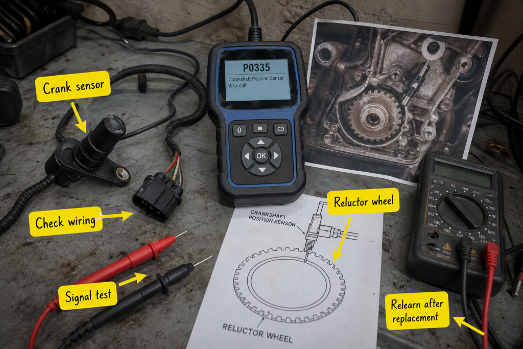
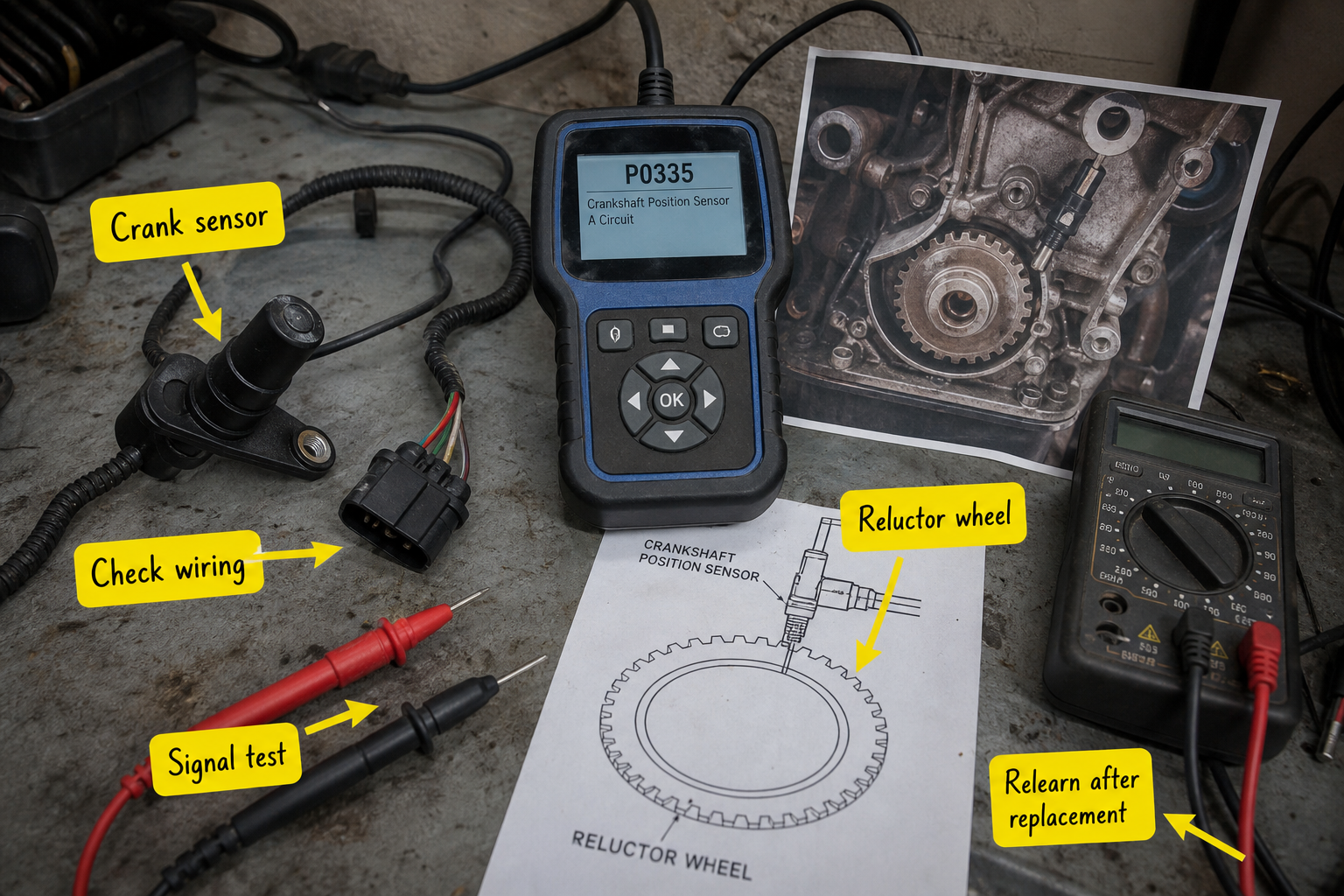
A diesel engine assembly line stops when the commissioning technician sees P0335 — crankshaft position sensor circuit malfunction — flash on the diagnostic scanner. Before ordering a replacement sensor, the technician measures reluctor ring tooth runout at 0.008 inches, checks sensor air gap at 0.045 inches against the 0.020–0.040 inch specification, and finds ferrous debris bridging the gap. The sensor itself tests within resistance range, but the crankshaft’s damaged reluctor wheel causes the false code.
Repairing a crankshaft sensor issue requires verifying whether the fault originates in the sensor, its wiring harness, the crankshaft’s reluctor ring or tone wheel, or the engine control module’s relearn state. Sensor replacement solves electrical failures, but crankshaft surface damage, excessive runout, or incorrect air gap must be corrected on the crankshaft itself. This guide covers diagnostic sequences, sensor replacement procedures, wiring inspection, reluctor ring condition checks, and ECM relearn requirements from a crankshaft manufacturing and repair perspective.
Key Takeaways
- Crankshaft sensor faults stem from sensor failure, reluctor ring damage, air gap deviation, wiring shorts, or ECM relearn loss after battery disconnect.
- Diagnosis begins with code reading, followed by resistance testing (typically 200–1,000 ohms for inductive sensors), air gap measurement, and reluctor ring inspection for tooth wear or runout.
- Sensor replacement requires torque-controlled installation, air gap verification with feeler gauges, and connector pin cleaning to prevent repeat codes.
- Reluctor ring damage including missing teeth, excessive runout beyond 0.005 inches, or debris accumulation requires crankshaft removal and machining or ring replacement.
- ECM relearn procedures reset fuel trim and timing maps after sensor replacement; skipping relearn causes rough idle and misfire codes on many platforms.
Diagnostic Sequence for Crankshaft Sensor Codes
Start diagnostics by retrieving stored codes with a scan tool. P0335, P0336, P0385, and P0386 indicate crankshaft position sensor circuit faults, while P0016 and P0017 point to correlation errors between crankshaft and camshaft sensors. Record freeze-frame data showing engine speed and load when the code set.
Measure sensor resistance with the harness disconnected. Inductive sensors typically show 200–1,000 ohms; Hall-effect sensors require 5-volt reference supply verification instead. Resistance outside specification confirms sensor failure.
Check air gap between sensor tip and reluctor ring teeth using a feeler gauge or by measuring sensor installation depth. Most inductive sensors require 0.020–0.040 inch clearance. Excessive gap from loose mounting or worn teeth prevents signal generation. Insufficient gap causes debris bridging and intermittent codes.
Inspect the reluctor ring or tone wheel on the crankshaft nose or counterweight for damage. Rotate the crankshaft manually and verify each tooth is present, without cracks, chips, or burrs. Measure radial runout at the reluctor ring outer diameter with a dial indicator mounted to the block; runout exceeding 0.005 inches degrades signal quality.
Sensor Replacement Procedure and Mounting Specifications
Remove the sensor by disconnecting the electrical connector and extracting the mounting bolt. Clean the sensor bore in the engine block or timing cover with a wire brush to remove carbon deposits and debris. Check for thread damage in the mounting hole; damaged threads require helicoil inserts before sensor installation.
Install the new sensor with a thread sealant rated for oil exposure if the bore intersects pressurized oil passages. Torque to manufacturer specification, typically 8–12 N·m (71–106 lb-in) for M6 fasteners or 20–25 N·m (15–18 lb-ft) for M8 fasteners. Over-torque cracks the sensor body; under-torque allows vibration and connector pin fretting.
Verify air gap after installation. If the sensor uses a fixed mounting depth, confirm proper seating by measuring protrusion from the block face. Adjustable sensors require feeler gauge measurement between the sensor tip and reluctor ring tooth crown, then locknut torque to prevent drift.
Clean connector pins with contact cleaner and inspect for corrosion, bent terminals, or moisture intrusion. Corroded connectors cause intermittent codes that mimic sensor failure. Apply dielectric grease to pins before reconnection to seal against moisture.
Wiring Harness Inspection and Continuity Testing
Disconnect both ends of the sensor harness and test continuity from the sensor connector to the ECM connector. Signal wire resistance should measure under 5 ohms; shield or ground wire resistance should measure under 1 ohm. Open circuits indicate broken wires inside insulation or corroded crimps.
Check for short circuits by measuring resistance between signal wires and ground with the harness disconnected. Infinite resistance confirms isolation; low resistance indicates damaged insulation or crushed wires where the harness contacts sharp edges or hot exhaust components.
Inspect the harness routing for interference with moving parts, heat sources, or high-voltage ignition wires. Magnetic inductive sensors generate low-voltage AC signals easily disrupted by electromagnetic interference. Reroute the harness away from alternator output cables and spark plug wires if cross-talk is suspected.
Test the ECM power supply to the sensor if using a Hall-effect or magnetoresistive sensor. These active sensors require 5-volt or 12-volt reference from the ECM. Measure supply voltage at the sensor connector with the key on, engine off. Low voltage indicates ECM internal faults or supply circuit damage.
Reluctor Ring Condition and Crankshaft Repair Limits
Reluctor ring damage requires crankshaft removal for inspection and repair. Common failures include missing teeth from impact damage during engine assembly, crack propagation from press-fit stress concentrations, and wear from contaminated oil abrasive particles.
Measure reluctor ring radial runout by mounting the crankshaft in V-blocks or between lathe centers. Position a dial indicator perpendicular to the reluctor ring outer diameter and rotate the crankshaft through 360 degrees. Runout exceeding 0.005 inches (0.13 mm) requires correction.
If the reluctor ring is integral to the crankshaft forging, runout correction requires grinding the reluctor ring diameter on a crankshaft grinder using a formed wheel matching the tooth profile. Grind only enough material to achieve concentricity; reducing tooth height degrades signal amplitude.
For pressed or welded reluctor rings, replacement is the standard repair. Heat the crankshaft snout to 150–200°C to expand the bore, then press off the damaged ring. Install the replacement ring with proper interference fit (typically 0.02–0.04 mm on diameter) to prevent slip under torsional vibration.
Reluctor Ring Failure Mode | Diagnostic Evidence | Repair Action | Crankshaft Removal Required |
Missing or damaged teeth | Intermittent code, no-start when crankshaft stopped at gap position | Ring replacement or tooth welding and profiling | Yes |
Excessive runout (>0.005 in) | Intermittent code during acceleration, signal amplitude variation | Grind integral ring or replace pressed ring | Yes |
Corrosion or debris buildup | Intermittent code, reduced air gap measurement | Clean with wire brush and solvent, verify air gap | No if accessible |
Press-fit slip | Code after high-RPM operation, circumferential witness marks | Replace ring with increased interference fit | Yes |
ECM Relearn and Fuel Trim Reset Procedures
After replacing the crankshaft position sensor, many engine control modules require a relearn procedure to recalibrate timing maps and fuel trims. Battery disconnect or sensor replacement erases adaptive values stored in ECM memory.
Idle relearn typically requires starting the engine and allowing idle speed stabilization for 5–10 minutes without load, with air conditioning and electrical accessories off. The ECM relearns target idle speed and adjusts throttle position or idle air control valve duty cycle.
Throttle position sensor relearn may be necessary on drive-by-wire systems. This procedure usually involves key-on with the throttle pedal fully released, then fully depressed, then released again to teach the ECM the full pedal travel range.
Crankshaft position variation relearn teaches the ECM the individual tooth spacing on the reluctor ring, allowing compensation for manufacturing tolerances. This procedure requires a scan tool with bidirectional control to command the relearn function while the engine runs at specified RPM and load conditions.
Skipping relearn procedures results in rough idle, hesitation, reduced power, and secondary codes for fuel trim limits or catalyst efficiency. Consult OEM service information for platform-specific relearn sequences, as procedures vary by manufacturer and model year.
Material and Surface Finish Requirements for Reluctor Rings
Reluctor rings on crankshafts must use ferromagnetic materials to generate inductive sensor signals. Common materials include 1018 low-carbon steel for pressed rings and 4140 alloy steel for integral forged reluctor wheels on performance crankshafts.
Surface finish on reluctor ring teeth affects sensor signal quality. Roughness average (Ra) should not exceed 3.2 micrometers (125 microinches) on tooth faces. Excessive roughness from grinding chatter or corrosion increases air gap variation and signal noise.
Heat treatment of reluctor rings depends on application. Pressed rings for passenger car engines typically use as-rolled 1018 steel without hardening. Diesel engine crankshafts with integral reluctor wheels receive induction hardening to 50–55 HRC to resist wear from oil contamination and vibration.
Tooth profile geometry must maintain consistent amplitude across all teeth. Symmetric tooth flanks with 30–45 degree angles and equal tooth width to gap width provide optimal signal generation. Tooth tip radius should be 0.5–1.0 mm to concentrate magnetic flux without creating stress concentrations.
FAQs
Can a crankshaft sensor be repaired or must it always be replaced?
Crankshaft position sensors cannot be repaired and must be replaced when internal windings fail or the sensing element degrades. However, many sensor codes result from correctable issues including wiring damage, connector corrosion, air gap problems, or reluctor ring damage. Verify the sensor itself has failed through resistance testing and signal scope analysis before replacement.
What causes repeated crankshaft sensor failures after replacement?
Repeated sensor failures indicate unresolved root causes. Excessive crankshaft runout from main bearing wear creates variable air gap and sensor tip contact damage. Reluctor ring debris from manufacturing burrs or engine wear accumulates in the sensor gap. Incorrect air gap from improper sensor installation or wrong part number causes thermal cycling damage. Electrical system faults including voltage spikes from alternator diode failure also destroy sensors. Inspect crankshaft runout, reluctor ring condition, and electrical system quality before installing another sensor.
Does crankshaft grinding affect reluctor ring position and sensor function?
Crankshaft grinding for journal repair does not affect pressed reluctor rings on the crankshaft nose but can disturb integral reluctor wheels machined into counterweights. When grinding counterweights for balance correction, maintain reluctor tooth geometry or mill a new tooth pattern after grinding. Verify reluctor ring position relative to main bearing centerline after grinding to ensure sensor mounting boss alignment. Some remanufacturers press off and reinstall reluctor rings after grinding to guarantee position accuracy.
How does crankshaft material selection impact sensor signal quality?
Crankshaft material affects sensor signal only if the reluctor ring is integral to the forging. Forged steel crankshafts in 4140, 4340, or micro-alloyed grades provide adequate magnetic permeability for inductive sensors. Billet crankshafts machined from similar alloys perform identically. However, nodular iron crankshafts common in passenger car engines have lower permeability and may require pressed steel reluctor rings to achieve sufficient signal amplitude. Exotic materials including titanium for racing applications require pressed ferromagnetic reluctor rings, as titanium is non-magnetic.
Conclusion
Crankshaft sensor repair success depends on separating sensor electrical faults from crankshaft mechanical issues and wiring problems. Begin diagnosis by measuring sensor resistance and air gap, then inspect reluctor ring condition for damage, runout, and debris that degrades signal quality. Replace sensors that fail electrical tests using correct torque and air gap specifications. Address wiring harness damage, connector corrosion, and ECM relearn requirements to prevent repeat codes. When reluctor ring damage exceeds field repair limits, remove the crankshaft for ring replacement or grinding correction. Complete ECM relearn procedures after sensor replacement to restore engine performance and prevent secondary fault codes.