
A marine diesel rebuild shop in Louisiana rejected a replacement crankshaft last year when magnetic particle inspection revealed subsurface porosity in two main journals. The part had arrived with correct dimensions and surface finish, but the casting process used by the supplier left internal voids that would have failed under cyclic loading within the first season.
Crankshafts are manufactured through three primary methods: forging, casting, and billet machining. Forging compresses heated steel billets into near-net shape using progressive dies, producing grain flow that follows stress lines. Casting pours molten iron or steel into sand or permanent molds, allowing complex geometry at lower cost. Billet machining removes material from solid bar stock, offering maximum design flexibility for performance applications. Each process is selected based on production volume, material properties, dimensional tolerances, and application loads.
Key Takeaways
Forged crankshafts offer superior fatigue strength because grain structure aligns with the part geometry, but tooling costs limit this method to high-volume production or racing applications. Cast crankshafts accommodate complex counterweight shapes and internal oil passages at lower per-unit cost, making them standard in most automotive and light industrial engines. Billet crankshafts provide maximum journal concentricity and custom stroke dimensions, but machining time restricts them to motorsport and prototype work.
Manufacturing method determines repairability. Forged crankshafts typically allow one regrind of 0.010 inch on mains and rods before grain structure interruption becomes a concern. Cast crankshafts with nodular iron composition can be reground if inspection confirms no subsurface porosity. Billet crankshafts maintain uniform properties through the cross-section and support multiple regrinds if initial journal diameters were oversized.
Forging Process and Material Flow
Forging begins with heated steel billets, typically AISI 1045 or 4340 alloy, raised to 1150-1250°C in induction or gas furnaces. The billet passes through a series of impression dies that progressively form the main and rod journals, counterweights, and flanges.
Grain flow follows the crankshaft contour because metal displacement during forging elongates the crystalline structure rather than cutting through it. This directional strength resists the alternating tension and compression loads at fillet radii where stress concentration is highest.
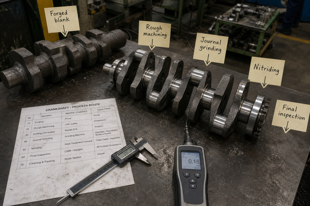
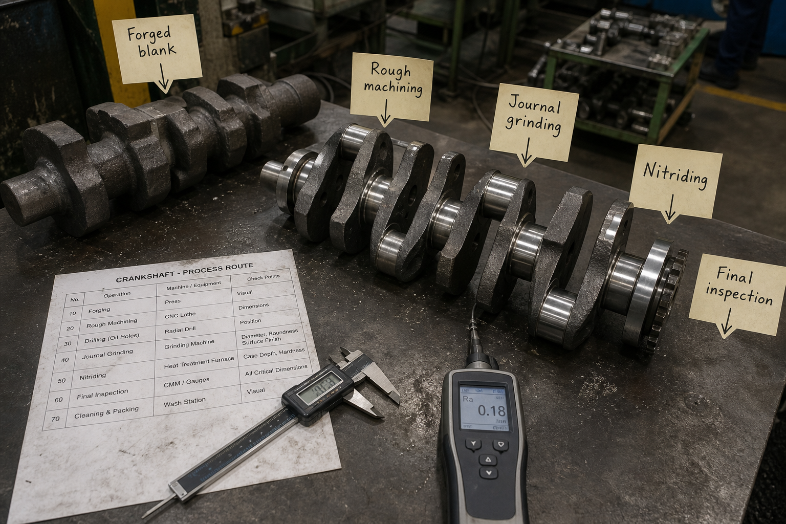
Flash trimming removes excess material at the parting line, followed by thermal normalization to relieve internal stress. Forged crankshafts then undergo rough machining to establish bearing journal diameters, oil hole drilling, and fillet rolling to induce compressive residual stress at fatigue-critical transitions.
The forging process requires dedicated tooling for each stroke and journal configuration. A single die set can cost $50,000 to $150,000, making this method economical only above 10,000 units per year or for applications where fatigue life justifies the investment.
Casting Methods and Porosity Control
Sand casting uses expendable molds formed around patterns, with cores defining internal oil passages and counterweight cavities. Molten gray iron or ductile iron at 1400-1500°C fills the mold cavity under gravity or low pressure. Solidification time ranges from 15 to 45 minutes depending on section thickness.
Ductile iron casting, also called nodular iron, adds magnesium to the melt to form spherical graphite nodules instead of flakes. This microstructure provides 60-80% of forged steel strength while maintaining the cost advantage and complex geometry capability of casting.
Permanent mold casting uses metal dies with better dimensional control and faster cooling rates than sand. This process reduces porosity risk but increases tooling cost and limits geometric complexity because the mold must allow part ejection.
Porosity forms when dissolved gases precipitate during solidification or when shrinkage creates internal voids. Casting facilities control this through degassing treatment, riser design to feed shrinkage, and chill placement to direct solidification progression. Magnetic particle inspection after machining reveals subsurface defects before the crankshaft enters service.
Billet Machining for Custom Applications
Billet crankshafts begin with solid bar stock, typically 4340 steel in the annealed condition. CNC turning establishes main and rod journal diameters, with the crankshaft rotating on centers while cutting tools traverse along the axis.
Counterweight profiles are milled or wire-EDM cut after journal machining. This method allows asymmetric counterweight shapes optimized for specific firing orders or to clear chassis components in tight installations.
Journal concentricity on billet crankshafts can reach 0.0002 inch total indicated runout because machining references from precision centers without repositioning. Forged and cast crankshafts typically show 0.001 to 0.003 inch runout after rough machining due to material stress relief and multiple setups.
Stroke dimension adjustments require only program changes rather than new tooling. A builder developing a stroker engine can specify a 0.250 inch stroke increase without the six-month lead time and tooling cost associated with forging dies.
Billet machining removes 60-75% of the starting material as chips, creating significant waste compared to near-net-shape forging or casting. This material efficiency penalty limits billet crankshafts to applications where custom dimensions or maximum precision justify the cost multiplier of 3x to 8x over equivalent cast or forged parts.
Heat Treatment and Hardening
Regardless of initial manufacturing method, most crankshafts undergo induction hardening of bearing journal surfaces. The crankshaft rotates while an induction coil heats a narrow band to austenitizing temperature, followed immediately by water or polymer quench.
Surface hardness after induction treatment reaches 58-62 HRC to a depth of 0.060 to 0.120 inch, while the core remains at 25-35 HRC. This hardness gradient provides wear resistance at the journal surface while maintaining core toughness to absorb impact loads.
Nitriding offers an alternative surface treatment that diffuses nitrogen into the steel at 500-530°C without a quench. Nitrided journals reach 60-70 HRC with minimal distortion, but the process requires 20-40 hours and adds significant cost. High-performance diesel and aircraft crankshafts often specify nitriding when dimensional stability is critical.
Final Machining and Balancing
Finish grinding brings journal diameters to final size with surface finish of 8-16 microinches Ra. Cylindrical grinding maintains diameter tolerance of ±0.0005 inch and minimizes taper and out-of-round conditions that cause bearing wear.
Oil holes are chamfered and deburred to prevent stress risers. Fillet radii receive final rolling to maximize compressive stress at the journal-to-counterweight transition where bending fatigue cracks typically initiate.
Dynamic balancing corrects mass distribution around the rotation axis. The crankshaft spins at moderate speed while sensors detect vibration amplitude and phase angle. An operator then drills material from counterweights or attaches balance weights until residual unbalance falls below 5-15 gram-millimeters depending on engine speed range.
Production crankshafts typically balance to ISO 1940 Grade G16, allowing 16 mm/s vibration velocity. Racing crankshafts require Grade G2.5 or better, demanding multiple balancing iterations and selective assembly with connecting rods and pistons matched within 2-gram tolerance.
Inspection Requirements and Defect Detection
Magnetic particle inspection applies ferromagnetic particles to the crankshaft surface while a magnetic field is active. Surface and near-surface cracks trap particles, creating visible indications under UV light. This method detects fatigue cracks at fillet radii and grinding burns that compromise material strength.
Ultrasonic inspection sends high-frequency sound waves through the crankshaft to detect internal defects. A loss of signal or echo pattern change indicates porosity, inclusions, or laminations. Cast crankshafts require ultrasonic inspection because visual examination cannot reveal internal voids.
Journal diameter, taper, and out-of-round measurements use micrometers or bench centers with dial indicators. Specification limits typically allow 0.0005 inch taper and 0.0005 inch out-of-round on new crankshafts. Worn or reground journals must stay within 0.001 inch total variation to prevent oil film breakdown.
Selecting Manufacturing Method by Application
Automotive original equipment uses cast ductile iron crankshafts for gasoline engines below 250 horsepower and diesel engines below 150 horsepower per liter. Manufacturing cost scales with production volume, and casting provides adequate fatigue life when fillet radii and surface finish meet design specifications.
Forged steel crankshafts appear in high-output engines where specific power exceeds 80 horsepower per liter or where sustained high-RPM operation demands superior fatigue resistance. The material cost premium of 40-60% over cast iron is offset by extended service intervals and reduced warranty exposure.
Marine and stationary power applications often specify forged crankshafts even at moderate power density because service life requirements extend to 20,000-40,000 hours between overhauls. The grain flow advantage of forging delays fatigue crack initiation under continuous-duty loading patterns.
Billet crankshafts serve motorsport and experimental installations where custom stroke, journal diameter, or counterweight configuration prevents use of catalog parts. Lead time drops from six months to six weeks compared to forging tooling, allowing rapid prototype iteration.
FAQs
Can a cast crankshaft be reground multiple times?
Reground depth is limited by wall thickness at oil passages and by subsurface porosity in cast iron. Most cast crankshafts allow one regrind of 0.010 inch, with some premium castings rated for 0.020 inch removal. Ultrasonic inspection before and after grinding confirms that no internal voids have been exposed.
How do you identify a forged versus cast crankshaft?
Forged crankshafts show parting lines where flash was trimmed, typically visible as a narrow ridge along the crankshaft axis. Cast crankshafts display a rougher as-cast surface on non-machined areas and often include cast identification numbers. Weight difference is also diagnostic: a forged steel crankshaft weighs 15-25% more than an equivalent cast iron unit.
What causes a crankshaft to fail after grinding?
Grinding burn removes surface hardness by overheating the journal during material removal. The softened surface shows a blue or brown temper color and wears rapidly under load. Magnetic particle inspection detects the metallurgical damage as a change in magnetic permeability. Proper grinding uses sharp wheels, adequate coolant flow, and shallow depth of cut to prevent thermal damage.
Do all manufacturing methods require balancing?
Yes. Forging, casting, and billet machining all produce mass variation that exceeds acceptable limits for smooth operation. Counterweight shape and density variation, core shift in casting, and machining tolerance stack-up create unbalance that must be corrected. Even race-prepared crankshafts require rebalancing after journal grinding because material removal alters mass distribution.
Conclusion
Manufacturing method selection depends on production volume, material properties, dimensional precision, and application duty cycle. Cast crankshafts dominate production engines because tooling cost amortizes across high volumes and material properties meet design life requirements when porosity is controlled. Forged crankshafts justify their cost premium in high-output or continuous-duty applications where superior fatigue strength extends overhaul intervals. Billet machining serves custom and prototype work where dimensional flexibility outweighs material efficiency.
Regardless of manufacturing process, magnetic particle inspection, ultrasonic testing, and dimensional verification are non-negotiable quality gates. A properly manufactured cast crankshaft with clean inspection results will outlast a forged unit with subsurface defects or grinding damage. Confirm inspection documentation and dimensional reports before accepting any replacement crankshaft, and verify that the manufacturing method matches the application’s load spectrum and service life requirements.